崇州市16400平方米医院门诊部暖通设计(含CAD图)

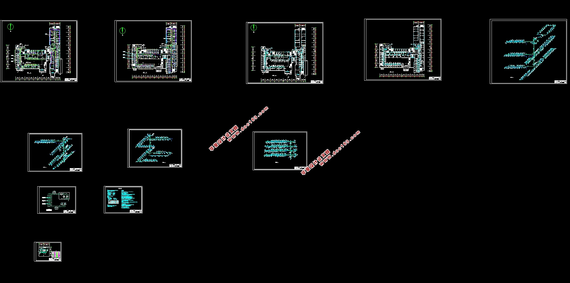
崇州市16400平方米医院门诊部暖通设计(含CAD图)(设计说明书14500字,外文翻译,CAD图纸10张,PDF图11张)
摘要
本课题是对崇州市门诊大楼各功能区及房间进行暖通空调设计,根据夏热冬冷地区的气候特征和建筑所在地区的地理位置特征,来综合考虑建筑所需的冷热源以及空调形式。医院这类建筑里,因其对设备功能的实际运行有较高的要求,而且建筑能耗较大,和常规的民用建筑不同。结合当地地下水资源丰富,所以最终冷热源采取水源热泵的形式。医院作为高耗能建筑,合理地规划暖通设计将会大大降低每年的能源消耗,响应国家提倡的节能号召。
本建筑采用鸿业暖通计算负荷,手算部分房间进行负荷验证,并对整个建筑进行负荷分析。医院对空气品质要求较高,人流密度一直稳定且较为密集,但是因为各个房间的使用用途的不一致,所以这里我们需要根据不同房间的使用来进行系统分区。最后确定医院门诊部的手术室和放射科使用的全空气空调形式,其他的各个诊室和医院办公建筑使用 的形式。
关键词:节能 水源热泵 软件
Abstract
This subject is to design hvac for each functional area and room of the out-patient building in ChongZhou city. According to the climate characteristics of hot summer and cold winter areas and the geographical location characteristics of the building area, it will comprehensively consider the cold and hot sources and air conditioning forms required by the building. In the medical building system, there are strict requirements on the actual operation of its equipment function, and the building energy consumption is large, which is different from ordinary civil buildings. Hospitals are different from conventional civil buildings in that they have higher requirements on the actual operation of equipment functions and higher energy consumption.
This building uses hongye Hvac load calculation, manual calculation of part of the room load verification, and the whole building load analysis.The hospital has a high requirement for air quality, and the crowd density has been stable and relatively dense. However, due to the different USES of each room, we need to conduct system partition according to the use of different rooms.
Key words: Energy-saving; Water source heat pump; Software; Fan coil tube plus independent fresh air
工程概况
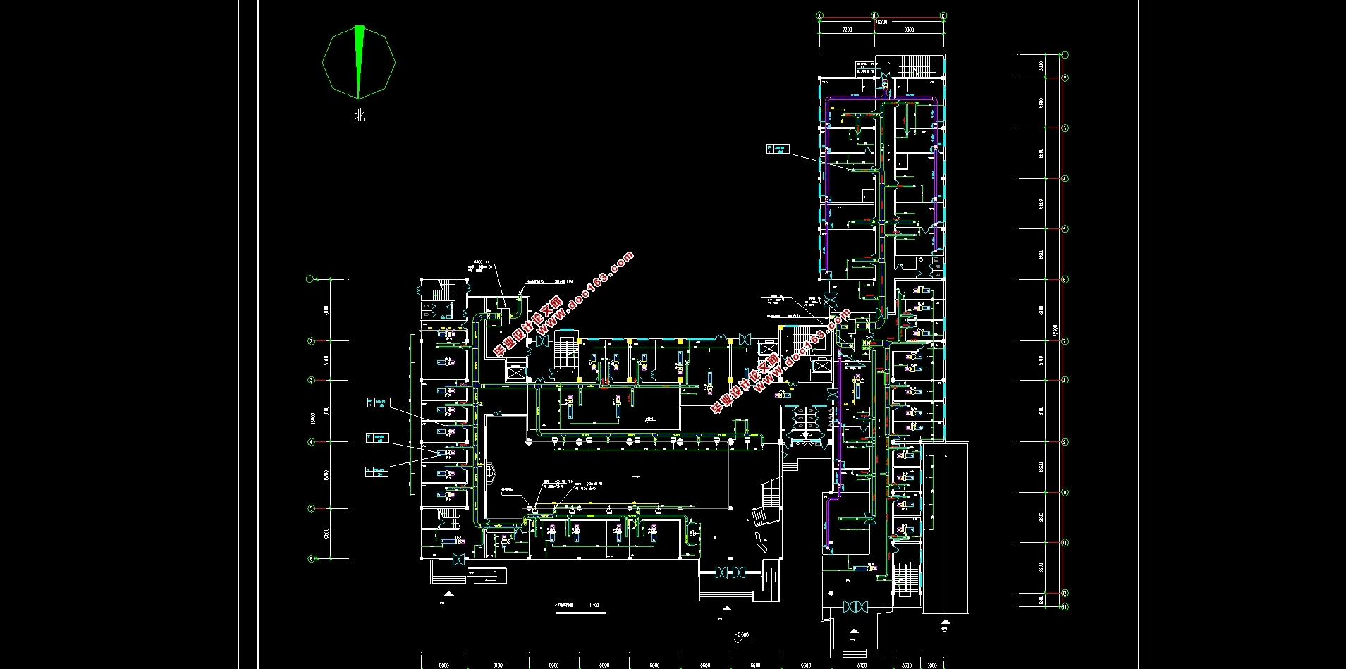
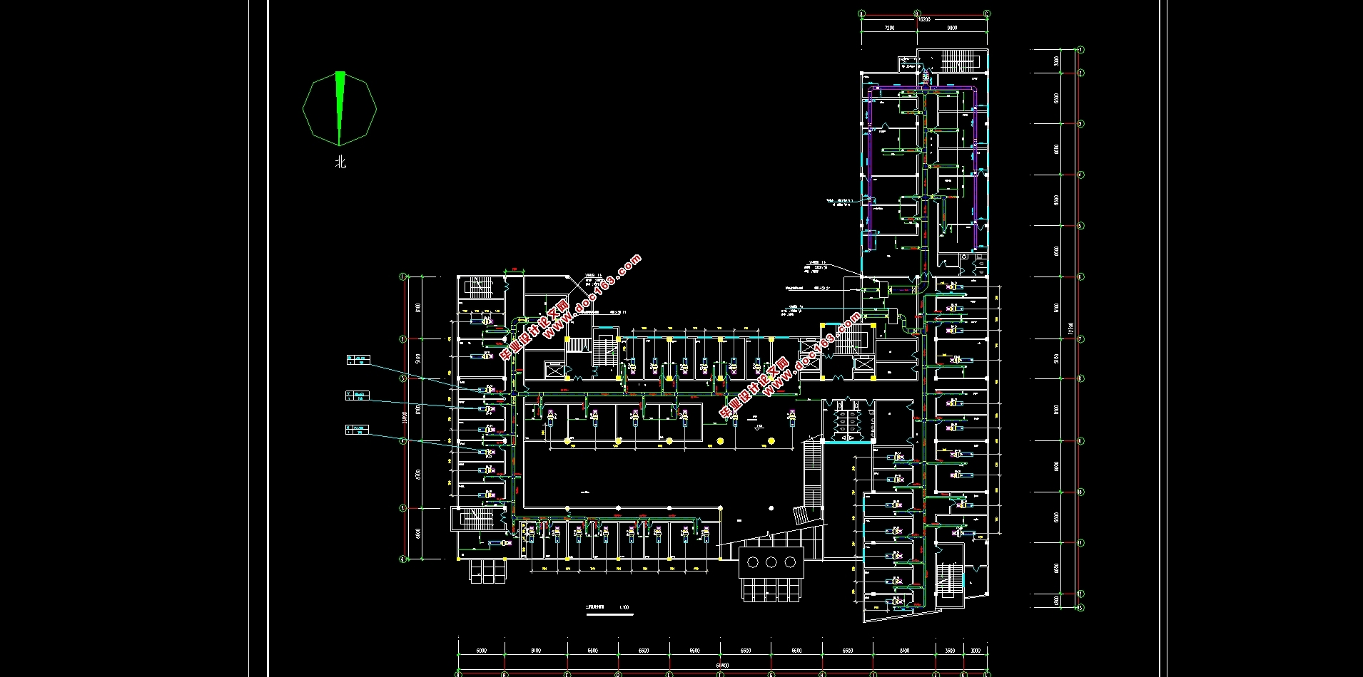
本项目位于四川省崇州市,总建筑面积约16400平方米,地下总建筑面积约2400平方米,地上总建筑面积约14000平方米,地下一层为地下车库及设备用房,地上10层,是集医院门诊、体检、办公教学、会议等为一体的综合门诊大楼。

目录
摘要 I
Abstract II
第一章 工程概况和建筑信息 1
1 .1工程概况 1
1.2 设计信息 1
1.2.1 室内外气象参数 1
1.2.2人员在室率与设备和灯光的使用率 2
1.2.3 其他参数值 3
1.2.4围护结构信息 4
第二章 负荷计算 6
2.1 空调冷负荷计算 6
2.1.1外墙与外窗的瞬时传热 6
2.1.2外窗日射得热 7
2.1.3内围护结构的传热冷负荷 7
2.1.4人体散热形成的冷负荷 7
2.1.5室内照明散热形成的冷负荷 8
2.1.6室内设备散热形成的冷负荷 8
2.2 负荷计算说明 9
2.3 手算和软件计算的对比 13
第三章 空调系统 14
3.1 空调系统确定 14
3.2 空调系统分区 15
3.3 全空气系统空调处理过程 16
3.3.1夏季处理过程 16
3.4 风机盘管处理方案 18
3.4.1新风处理方案 18
3.5 新风机组选型 20
3.6风盘选择 22
3.6.1 风机盘管选型 22
3.6.2 风机盘管的布置 22
第四章 冷热源确定 23
4.1建筑和地区特点 23
4.2 水源热泵技术分析 23
4.2.1 水质分析 23
4.3 系统配置 24
第五章 气流组织计算 26
5.1 气流组织计算目的 26
5.2 散流器计算 26
5.2.1风机盘管送回风口气流组织计算 26
第六章 风管水力计算 28
6.1空调风系统的水力计算 28
6.1.1空调风系统水力计算举例 28
6.2风口的布置 30
6.3风管的布置及附件 30
第七章 水管水力计算 31
7.1 水系统形式确定 31
7.1.1两管制水系统 31
7.1.2 闭式系统的特点 31
7.1.3 同程和异程系统的选择 31
7.1.4 一次泵变流量系统的选择依据 31
7.2水系统水力计算 33
7.2.1管材的选择和连接 33
7.2.2管径的确定 33
7.2.3沿程阻力 33
7.2.4局部阻力及局部阻力系数 34
7.2.5 水力计算举例 35
7.3 冷凝水管道设计 38
7.3.1 设计原则 38 [资料来源:www.doc163.com]
7.3.2 冷凝水管管径确定 38
7.3.3 冷凝水管的保温 39
7.3.4 水系统安装要求 39
7.4 膨胀水箱配置与计算 40
7.6集水器和分水器 42
第八章 冷热源设备选型设计 43
8.1 水泵的选型 43
8.1.1水泵设计规范 43
8.1.2 冷冻水泵的选型 44
8.2 换热器的计算选择 45
第九章 管道保温与设备消声 46
9.1 管道保温的一般原则 46
9.2 管道保温层厚度的确定 46
9.3 空调系统消声设计 46
9.4 空调系统减振设计 47
小结 48
参考文献 49
下一篇:苏州城区金融商务中心暖通工程施工组织设计(含横道图网络图)
