
基于PLC的数控机床控制设计(附梯形图程序)
资料介绍:
基于PLC的数控机床控制设计(附梯形图程序)(任务书,开题报告,外文翻译,论文20000字)
摘要
数控机床是机电一体化的数字控制装置,在工业生产中占着极大的比重,而且数控机床的先进水平也体现一个国家的工业生产水平。在早期的数控机床中,是利用继电器来实现控制。但继电器有着极大的缺点,例如体积大、线路多,出现问题时很难做出更改。继电器是一种硬接线系统,一旦出现问题,很难维修,因此可靠性也不高,影响正常生产。
为了解决继电器控制的缺点,本文采用PLC对数控机床进行重新设计。PLC使用软接线的方式对数控机床进行控制,避开了继电器硬接线的缺点。本文使用了西门子S7-200型PLC进行数控机床的控制设计,优化其控制性能。主要内容包括主轴、进给轴、换刀和紧急停止程序的设计。最后利用西门子STEP7-MICRO软件编写了相应的PLC控制程序的梯形图,并通过相关设备进行运行监控,观察了程序的运行情况。
本文采用模块化设计方法。将要设计的功能分成基本参数检查模块、主轴模块、进给轴模块、换刀模块及急停模块。不同模块相互独立,这样容易设计和更改。在绘制梯形图时,程序结构清晰,容易调试。
关键词:PLC、数控机床、梯形图
[来源:http://Doc163.com]
Design of NC Machine Tool Based on PLC Control
ABSTRACT
CNC machine tools are digital control devices combined of mechanical and electrical ,accounted for a great proportion in industrial production ,also reflect a country's industrial production level. the relays are applied to control CNC machine tools in the early age. But the relay has many drawbacks, such as large size, more lines, the accident difficult to make changes. Relay is a hard-wired system, once a problem happened, it is difficult to repair, also it is not reliable, and affecting the normal production.
In order to solve the shortcomings of relay control, this paper uses PLC to redesign CNC machine tools. PLC use soft wiring to control the CNC machine tools, to avoid the shortcomings of the relay hardwire. In this paper, Siemens S7-200 PLC is used to design of CNC machine tools, and optimizing its control performance. The main contents are the designs of the spindle, feed axis, tool change and emergency stop program. Finally, using the Siemens STEP7-MICRO software to write the corresponding PLC control program ladder diagram, and the relevant equipment is used to monitor the operation, observing the operation of the program. [资料来源:http://www.doc163.com]
This article uses the modular design method. The system is divided into basic parameter check module, spindle module, feed axis module, tool change module and emergency stop module. Different modules are independent of each other, so they will be easy to design and change. When drawing a ladder diagram, the program structure will be clear and easy to debug.
KEYWORDS: PLC, CNC machine tools,Ladder diagram
[资料来源:www.doc163.com]

目录
摘要Ⅰ
ABSTRACTⅡ
绪论Ⅵ
第一章 概述1
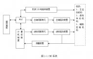
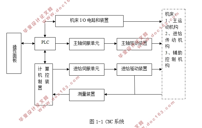
1.1 数控系统的工作原理1
1.1.1 数控系统的组成1
1.1.2 数控机床的工作原理及特点2
1.2 PLC的工作原理2
1.2.1 PLC的基本结构2
[资料来源:http://www.doc163.com]
1.2.2 PLC的功能3
1.2.3 PLC的工作原理3
1.2.4 PLC程序的设计方法和步骤4
1.3 本章小结5
第二章 数控机床与PLC的联系6
2.1 数控机床与PLC的信息传递6
2.2 数控机床中PLC的控制对象6
2.3 PLC的优势及继电器的劣势6
2.4 本章小结6
第三章PLC程序的设计7
3.1 西门子编程软件STEP7-MICRO介绍7
3.2 输入输出分配9
3.3 基本信号处理程序设计10
3.3.1 进给轴初始化程序10
3.3.2 CNC参数检查程序11
3.3.3 电动刀架参数检查程序12
3.3.4 进给轴回参考点程序13
3.4 进给轴控制程序设计14
3.4.1 驱动器延时程序15
3.4.2 CNC急停控制程序16
3.4.3 驱动器起停控制程序17
3.4.4 驱动器信号输出程序19
3.4.5 驱动器报警程序19
3.4.6 进给轴伺服使能控制程序20
3.4.7 进给轴进给使能控制程序22
[资料来源:http://www.doc163.com]
3.4.8 进给轴制动器控制程序23
3.5 主轴控制程序设计24
3.5.1 主轴正反转控制程序24
3.5.2 主轴报警输出程序25
3.5.3 主轴转向控制程序26
3.5.4 主轴手动控制程序27
3.5.5 主轴换向控制程序28
3.5.6 主轴停止程序29
3.5.7 主轴制动程序30
3.5.8 主轴信号输出程序31
3.5.9 主轴制动器延时程序32
3.6 电动刀架换刀程序设计33
3.6.1 电动刀架简介34
3.6.2 刀架初始化程序34
3.6.3 刀号转换程序35
3.6.4 T代码换刀程序37
3.6.5 换刀监控程序38
3.6.6 手动换刀程序40
3.6.7 换刀信号输出程序40
3.7 紧急停止程序41
3.7.1 行程保护程序43
3.7.2 超程方向输出程序44
3.7.3 急停链超程轴输出程序45
3.7.4 超程解除程序46
3.8 梯形图的调试48
[资料来源:http://doc163.com]
3.9 本章小结48
总结49
致谢51
参考文献52
附录54
附录Ⅰ 输入输出分配表54
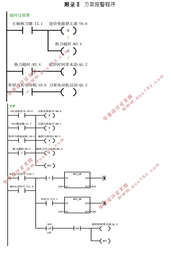
附录Ⅱ 刀架报警程序57
[版权所有:http://DOC163.com]
上一篇:西门子PLC串行通信技术