
基于solidworks的RTG40起升机构设计及虚拟装配(含CAD图,三维图)
基于solidworks的RTG40起升机构设计及虚拟装配(含CAD图,三维图)(任务书,开题报告,论文说明书9000字,CAD图纸4张,SolidWorks三维图)
摘要
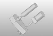
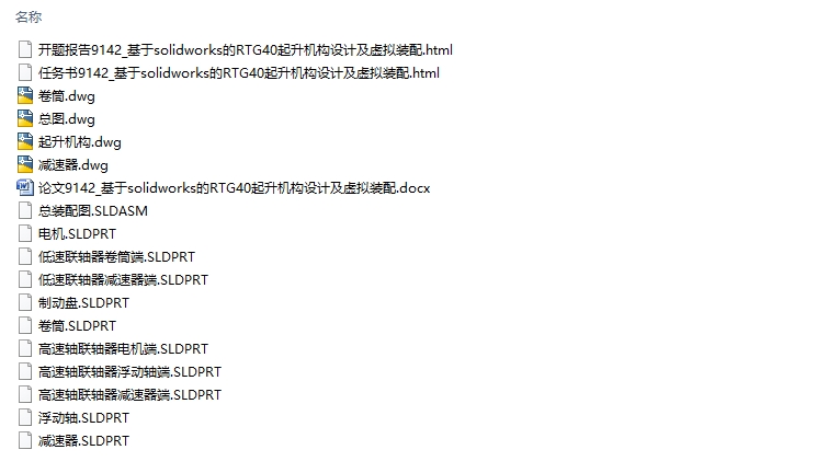
本文在给定RTG40基本参数的基础上,进行了对起升机构减速器、卷筒、电机、联轴器、制动器以及钢丝绳卷绕系统的计算和选型,并进行了强度和稳定性校核,完成了工作循环时间计算。利用AutoCAD绘制了主要零部件、起升机构及整机的三视图;利用SOLIDWORKS完成了对各零部件的建模并进行了虚拟装配。
论文主要研究了RTG40起升机构各零部件的作用及运行方式以及对整机工作的影响。
研究结果表明,本台轮胎式集装箱龙门起重机的起升机构能满足给定的起升速度、加速度、起重量等要求。
本文的特色:以计算为主,辅以部分CAD及SOLIDWORKS图片进行形象地介绍,条理分明,具有很强的逻辑性和说服力。
关键词:工作循环时间 传动方案 钢丝绳卷绕系统 过载校验 减速器 联轴器 高速浮动轴
Abstract
This article is based on the basic parameters of a given RTG40 ,the calculation and selection of hoisting mechanism reducer, drum, motor, coupling, brake and wire rope winding system are carried out. The strength and stability were checked, and the working cycle time was calculated.The three views of the main parts, lifting mechanism and the whole machine were plotted by AutoCAD.SOLIDWORKS is used to complete the modeling and virtual assembly of all parts. [资料来源:http://doc163.com]
This paper mainly studies the function and operation mode of each part of RTG40 lifting mechanism and its influence on the whole machine work.
The research results show that the lifting mechanism of the Longmen container crane can meet the requirements of lifting speed, acceleration and lifting weight.
The characteristics of this article:Take the calculation as the main part, supplemented by some CAD and SOLIDWORKS pictures to make an introduction.
The alticle is clear,logical and persuasive.
Key words: working cycle time transmission plan steel wire winding system overload check reducer coupling high speed floating shaft.
基本参数
参数名称 数值 备注
额定起重量t 吊具下 40
含吊具及上架 51
起升速度m/min 额定载荷 20
空载 40
起升加速时间s 额定载荷 20
空载 4
起升减速时间s 额定载荷 2
空载 4
跨距m 23.47 堆六列,集卡边置
起升高度m 15.24 吊具下,堆四过五
基距m 6.4
柴油机电动驱动
整机工作级别 A7
轮压t≤ 32


 [资料来源:Doc163.com]

目录
第1章 绪论 1
1.1引言 1
1.2 国内研究现状 1
1.3 国外研究现状 1
1.4 起重机的组成及基本工作原理 2
1.4.1 工作机构 2 [资料来源:http://doc163.com]
1.4.2 金属结构 2
1.4.3 动力装置及控制系统 3
1.5 主要设计内容 3
1.6 设计方法介绍 3
第2章 设计初始参数 5
2.1基本参数 5
2.2载荷计算 5
第3章 工作循环时间计算 7
第4章 起升机构的设计 12
4.1 起升机构传动方案的确定 12
4.2 八绳防摇机构的设计 13
4.3 钢丝绳的选取 13
4.4 滑轮的选取及相关尺寸的确定 14
4.4.1滑轮直径 14
4.4.2滑轮绳槽尺寸 15
4.5 确定卷筒尺寸并验算强度 15
4.5.1卷筒直径 15
4.5.2卷筒长度 16
4.5.3卷筒壁厚及卷筒的验算 16
4.5.4卷筒的绳端固定 17
4.5.5卷筒的转速 18
4.6 电机的选型及校核 18
4.6.1 起升静功率 18
4.6.2 加速功率 19
4.6.3 转动惯量加速功率 19
4.6.4 电机的发热校验 20
4.6.5 电机的过载校验 20
4.7 减速器的选用 20
4.8 联轴器及制动器的选型 22
4.8.1 高速轴联轴器的选型 22
4.8.2 低速轴联轴器的选型 22
4.8.3 制动器的选取 22
4.8.4 起、制动时间验算 23
4.9 高速浮动轴验算 24
4.9.1 疲劳验算 24
4.9.2 强度验算 25
第5章 环境影响与经济性分析 26
5.1 环境影响分析 26
5.2 经济性分析 26
第6章 结论 27
致谢 28
参考文献 29
上一篇:基于Delta机构的并联手控器设计(含CAD图,SolidWorks三维图)
下一篇:3T模锻电液锤控制系统的开发设计(含CAD图,ProE三维图)