可回转换刀的圆周平动车削刀架设计(含CAD图,SolidWorks三维图)
可回转换刀的圆周平动车削刀架设计(含CAD图,SolidWorks三维图)(任务书,开题报告,外文翻译,论文说明书11000字,CAD图6张,SolidWorks三维图)
摘 要
曲轴质量的好坏一定程度上决定了发动机的性能,进而影响汽车的质量,所以在汽车生产制造业中,能否加工出更高质量,更高的精度,更稳定的曲轴对企业来说至关重要。在曲轴的加工方法中,曲轴的跟随加工方法目前来说非常先进,它能够通过车削刀架解决在老式加工方法中存在的速度慢,时间长,耗费人力物力多等问题。设计一种较为合理刀架的结构对于曲轴的加工有着非常大的帮助,能够促进其发展。
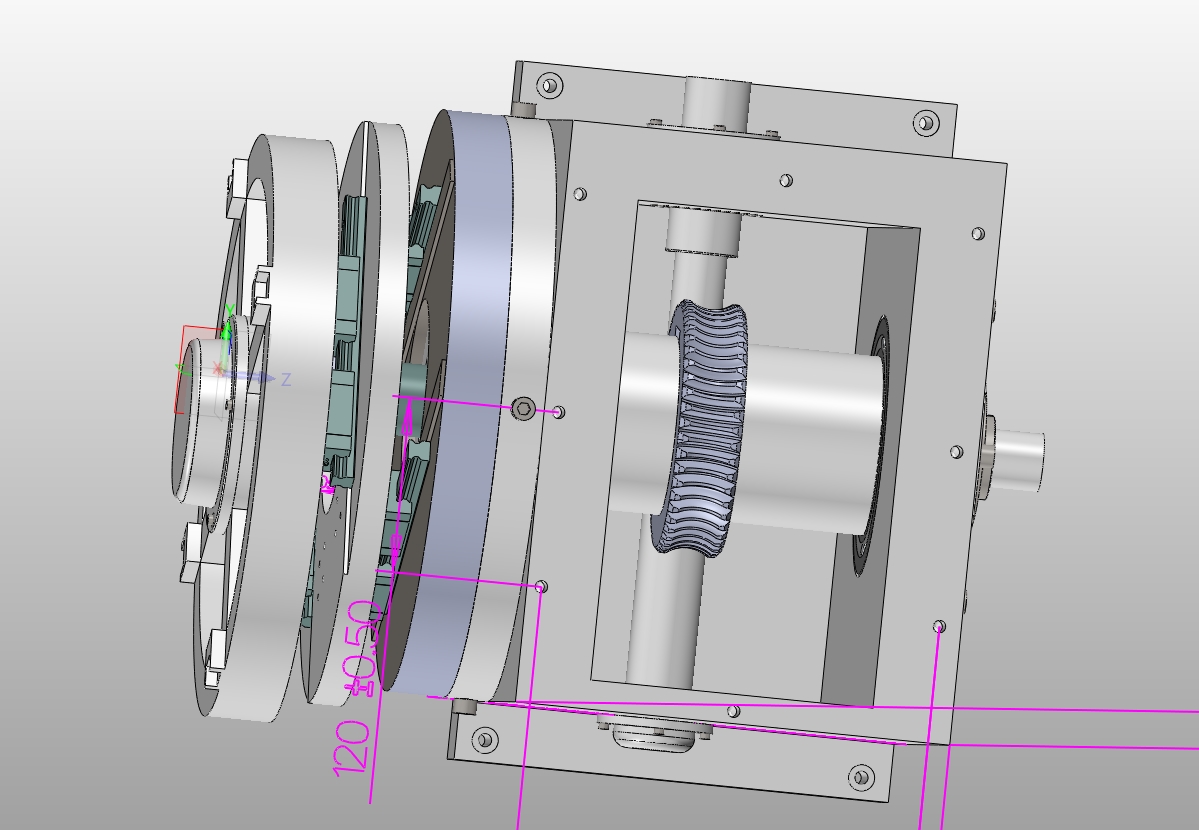
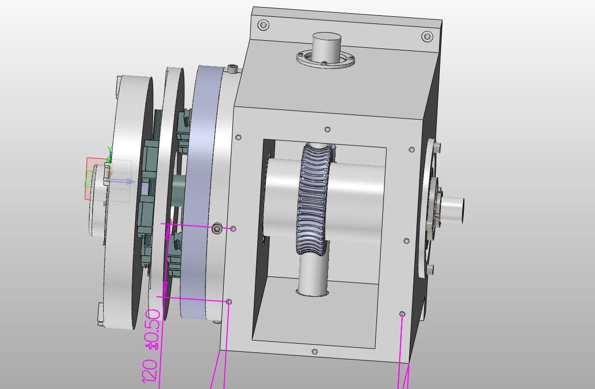
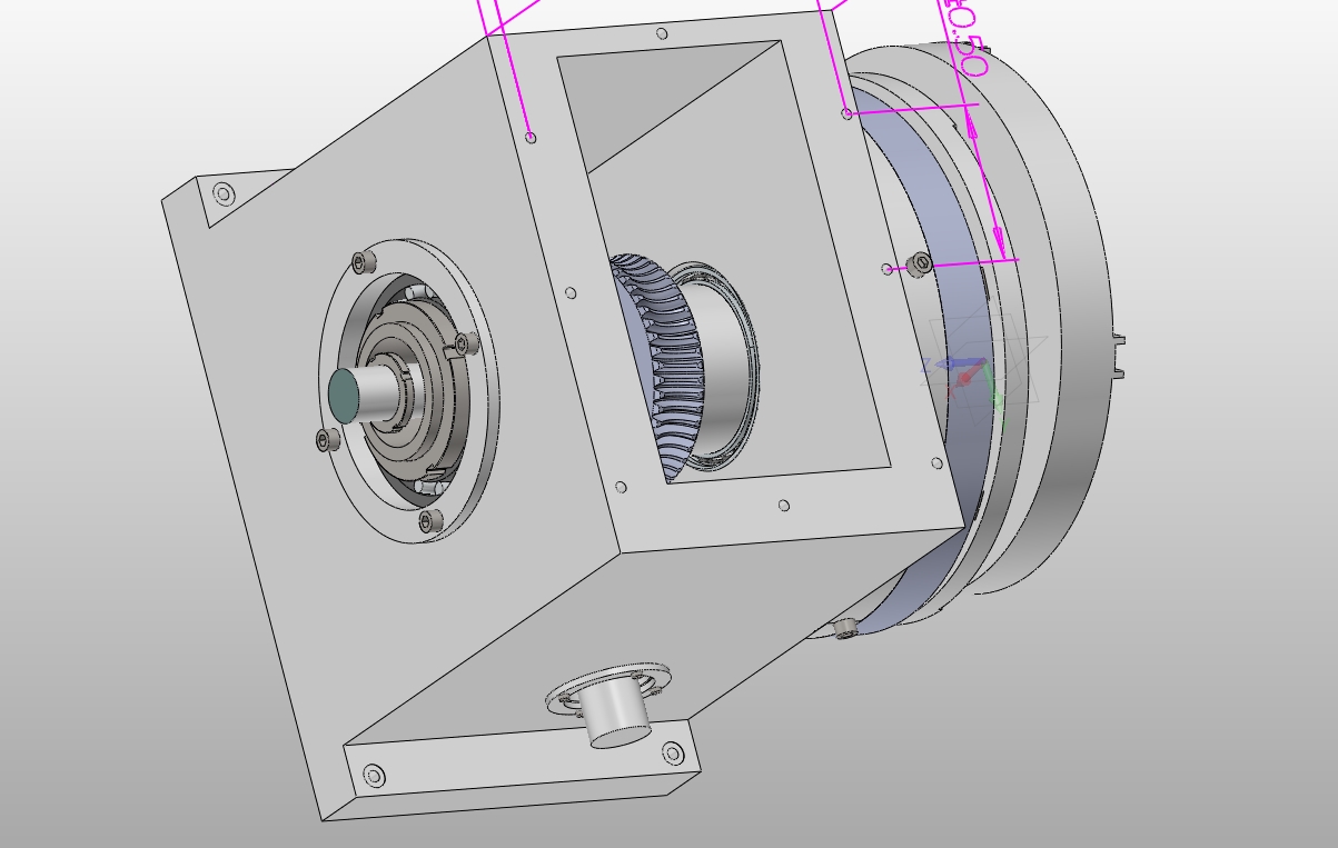
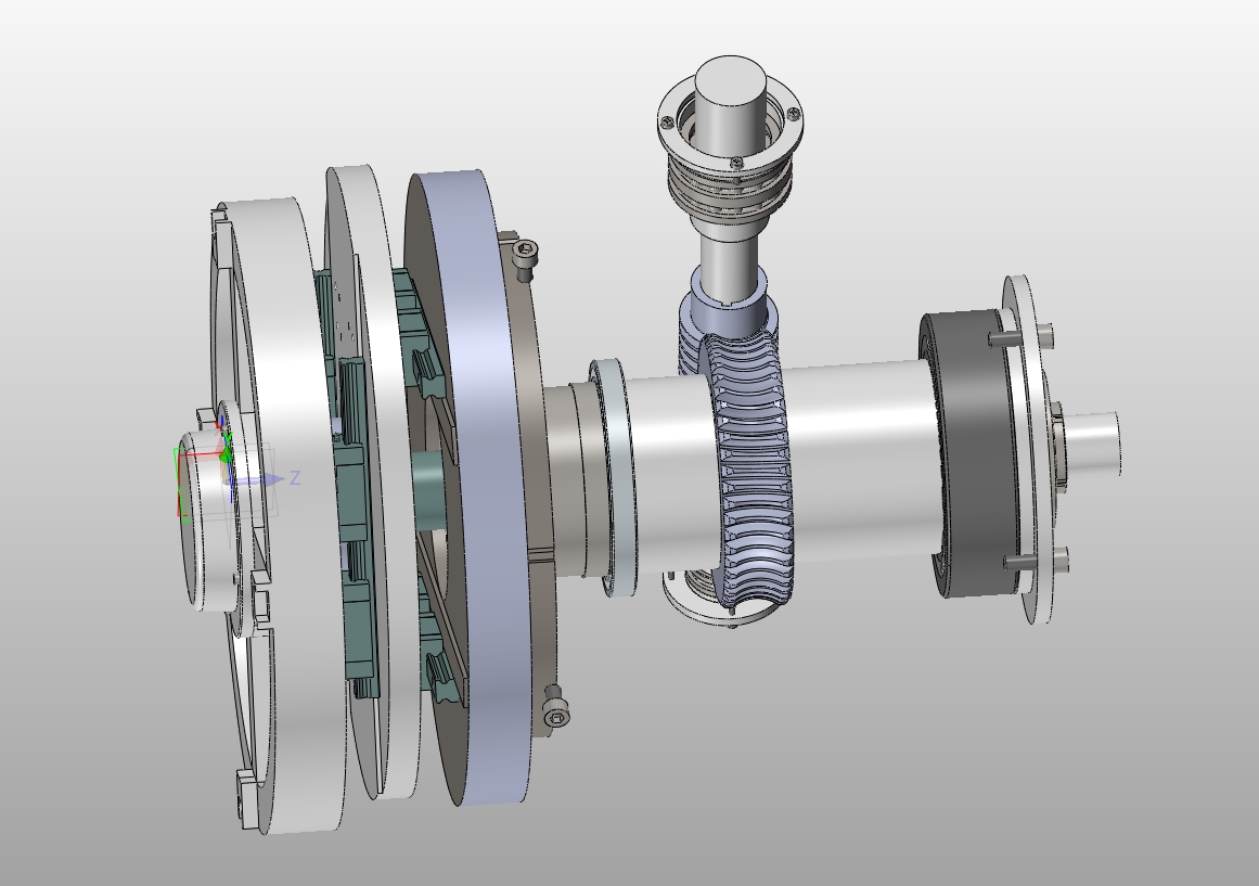
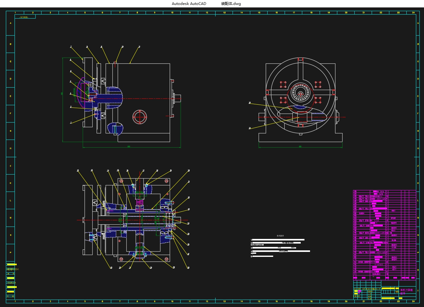
论文设计了一种能够自动换刀且在曲轴跟主轴一起旋转时能够跟随曲轴一起车削的刀架结构。首先论文对可回转换刀的圆周平动车削刀架结构的主要参数进行了设计,分别运用相关知识对两根主轴、蜗轮蜗杆、直线导轨进行了参数以及选型确定,同时对轴、直线导轨、滑块等主要部件惊行了力学分析、校核,结果显示设计的轴、直线导轨等主要部件符合在题目所给条件下的车削力要求。运用两个偏心轴实现了对可自动回转换刀的圆周平动车削刀架的运动轨迹半径可调要求。其次根据运用SolidWorks2016设计了可回转换刀的圆周平动车削刀架的三维模型,分别通过电机带动实心轴的转动,实心轴转动之后带动刀架的转动实现车削刀架的运动、两个直线导轨的运动实现XY方向的移动,这就类似于十字滑台的运动实现车削刀架的圆周平动、蜗杆带动蜗轮以及空心轴的转动最终实现自动换刀。最后运用AutoCAD建成了二维图,在实现题目要求的前提下,圆满完成了设计任务。
[资料来源:www.doc163.com]
关键词:复合跟随车削;自动换刀;圆周平动;轨迹半径可调
Abstract
The quality of the crankshaft determines the performance of the engine to a certain extent, thus affecting the quality of the car, so in the automobile manufacturing industry, whether the processing of a higher quality, higher accuracy, more stable crankshaft to the enterprise It is important. In the crankshaft machining method, the crankshaft machining compound follow-up turning process is a processing technology with high precision, high efficiency and high cutting speed. It can solve the problems in the old processing method by turning the tool holder, a long time, cost manpower and more material. The design of a more reasonable tool holder structure for the crankshaft processing has a very large help, to promote its development.
The paper has designed a turret structure that can be automatically turned and can be turned along with the crankshaft when the crankshaft rotates with the spindle. In this paper, the main parameters of the rotary turret structure of the rotary turning tool are designed. The parameters of the two main shafts, worm gear and linear guide rail are selected and identified by the relevant knowledge, and the shaft and the linear guide , Sliders and other major components of the mechanical analysis, check, the results show that the design of the shaft, linear guide and other major components in line with the conditions given under the conditions of the turning force requirements. The use of two eccentric shaft to achieve the automatic return tool for the circumference of the turning tool turret radius adjustable track requirements. Secondly, according to the use of SolidWorks2016 design of the rotary knife rotary turning tool turret of the three-dimensional model, respectively, through the motor to drive the rotation of the solid shaft to achieve the rotation of the turret, linear guide similar to the movement of the cross- Circle translation, worm-driven worm and the rotation of the hollow shaft to achieve the final automatic tool change, as well as the parts of the drawing, made into the assembly map. Finally, the use of AutoCAD built a two-dimensional map, in the realization of the requirements of the premise, the successful completion of the design task. [资料来源:https://www.doc163.com]
Key words:compound follow-up turning; automatic tool change; circle translation track
论文主要对减速机构中的蜗轮蜗杆进行设计计算,对实现圆周平动的直线导轨、两根主轴进行设计计算。车削刀架切削力为: =1150N, =790N, =2900N,根据市场上的曲轴连杆颈论文选择的偏心距变化范围从15-35mm。
减速机构的设计计算
论文采用的是蜗轮蜗杆减速。由于刀架体转位所需功率较小所以选择驱动刀架体转位的电机P=120w,额定转速 =1440 。设计选择蜗杆的传动比为50,换刀转速 =28.8 。论文采用的锁紧方式为螺纹锁紧,在空心轴和蜗轮停止转动后蜗杆会有一个轴向移动,会承受一部分冲击载荷,所以设计其使用寿命为 =12000h.
[资料来源:www.doc163.com]
 [来源:http://www.doc163.com]


[资料来源:https://www.doc163.com]
目录
第1章 绪论
1.1课题研究背景 1
1.2课题研究的意义 1
1.3与本课题有关的国内外研究现状 2
1.3.1国内外曲轴加工现状 2
1.3.2国内外曲轴车削加工自动换刀现状 2
第2章 总体方案设计 3
2.1自动刀架的基本要求和类型 3
2.1.1自动刀架的基本要求 3
2.1.2自动刀架的类型 3
2.2方案的拟定确定 4
第3章 总体结构设计 5
3.1减速机构的设计 5
3.2刀架抬起、锁紧机构的设计 5
3.3平面圆周回转运动机构设计 6
3.4圆周半径可调机构设计 7
第4章 车削刀架主要零件设计 9
4.1减速机构的设计计算 9
4.1.1蜗杆的选型 9
4.1.2蜗杆副的材料选择 9
4.1.3按齿面接触疲劳强度进行设计计算 9
4.1.4蜗杆和蜗轮的主要参数与几何尺寸 11
4.1.5校核蜗轮齿根弯曲疲劳强度 12
4.2实心轴、空心轴的设计 13
4.2.1选材 13
4.2.2计算实心主轴(刀架轴)所承受的扭矩 14
4.2.3实心主轴(刀架轴)的校核 15
4.3直线导轨的设计 17
4.3.1直线导轨的工作原理 17
4.3.2直线导轨的分类选型 17
4.3.3直线导轨的主要参数与校核分析 18
第5章 车削刀架三维设计与总结 20
5.1 SolidWorks软件介绍 20
5.2 部分零件建模过程 20
5.2.1 弹簧的画法 20
5.2.2 刀架装配图的画法 23
5.3 总结 24
参考文献 25
