
基于FPGA的DDS多波形信号源设计
基于FPGA的DDS多波形信号源设计(外文翻译,论文13000字)
摘要:多波形信号发生器在科学研究和教学实验等领域应用广泛。为了得到精度更高、稳定性更好、频率幅度相位可调的多种波形,本文研究直接频率合成器(DDS)原理,设计了一种基于现场可编辑门阵列(FPGA)的DDS信号发生器。利用Verilog硬件描述语言设计底层模块以及Quartus Ⅱ自带的模块构成DDS核,采用RAM存储数据,并将一个Nios Ⅱ软核处理器嵌在FPGA上,通过在Nios Ⅱ编写控制波形、频率、幅度、相位以及方波占空比的C语言程序,控制系统,从而能够实现任意波形实时输出。设计实验结果表明,与普通信号发生器以及其他基于FPGA的信号发生器相比,该方法实现的信号发生器能更加灵活产生多种波形,频率输出范围更大,方波占空比可调且更方便。
关键词:多波形信号发生器,FPGA ,DDS, Nios软核
Title:Design of DDS multi-waveform signal source based on FPGA
Abstract: Multi-wave signal generator is widely used in scientific research and teaching experiment. In order to get a variety of waveform whose frequency, amplitude and phase can be adjusted and which have higher precision and better stability,this paper studies the principle of direct frequency synthesizer (DDS) and designs a DDS signal generator based on field programmable gate array (FPGA) . Using Verilog hardware description language to design the underlying module, making use of DDS coremodule of Quartus Ⅱ, using the RAM to store data, and putting a Nios soft core processor Ⅱ to embed in the FPGA, writing control waveform, frequency, amplitude, phase and square wave duty ratio of the C language programby Nios Ⅱ to control system, which can realize arbitrary waveform real-time output. Experimental results show that in comparison to general signal generator and others which using FPGA signal generator, the method to realize the signal generator can be more flexible to produce a variety of waveform, frequency output range is bigger, adjustable square wave duty ratio and more convenient.
Key words: Multi-waveform signal generator,FPGA, DDS, Nios soft core
[资料来源:http://doc163.com]


目 录
第1章 绪论 1
第2章 系统方案设计 2
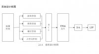
2.1 系统设计框图 2
2.2 总体方案设计分析 3
2.3 数据存储方案设计分析 4
第3章 直接数字频率合成器(DDS)的原理 4
3.1 DDS的原理 4
3.2 DDS的优缺点 6
3.3 DDS的应用 7
第4章 多波形DDS信号源硬件设计 7
4.1 硬件平台FPGA 7
4.2 DDS模块及内部 8
4.2.1 48位相位累加器 8
4.2.2 相位加法器 9
4.2.3 波形存储器 9
4.3 锁相环模块PLL 9
4.4 Nios Ⅱ软核处理器 10
4.5 D/A转换器和低通滤波器分析 11
4.6 键盘模块设计 13
第5章 多波形DDS信号源软件设计 13
5.1 软件平台Quartus Ⅱ和Nios Ⅱ 14
5.2 硬件描述语言 15
5.3 软核C编程 15
5.3.1 生成波形数据RAM表部分程序 15
5.3.2 键盘控制程序实现 18
第6章 系统功能验证及调试 20
6.1 实验仿真及验证 20
6.2 结果分析与调试 25
6.3 误差分析 25 [资料来源:http://Doc163.com]
第7章 总结与展望 26
致谢 27
参考文献 28
附录 29