
基于单片机的电阻电容电感测试仪的设计
基于单片机的电阻电容电感测试仪的设计(任务书,开题报告,外文翻译,论文10000字)
摘要
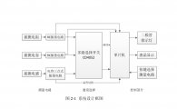
本设计介绍了以单片机为核心的电阻、电容、电感的测试仪。测量的原理是将振荡电路所产生的频率信号转化为对应的电阻、电容、电感值从而实现测量的。其中电阻和电容是由555多谐振荡电路产生的频率信号来测量的,而电感则是根据电容三点式振荡电路产生的频率信号来测量的。本设计中主控制器采用AT89C52单片机来实现控制。振荡电路将频率信号送入CD4052四选一电路选择器中,然后将被选择的信号送给单片机。单片机则调用相应的计算公式将被测器件值测量出来最后显示在液晶显示屏上。在系统的软件设计使用C语言编写了系统的应用软件,这些软件包括主程序模块、显示模块、电阻测试模块、电容测试模块和电感测试模块。
关键词: 单片机 测量 555定时器 频率
Microcontroller-based resistance capacitance and inductance tester
ABSTRACT
This design introduced the tester resistance, capacitance, inductance microcontroller as the core of the. The principle of the measurement is the frequency of the signal generated by the oscillator circuit is transformed into the corresponding resistance, capacitance, and inductance value so as to realize the measurement of. The resistance and capacitance is the frequency signal generated by the 555 multivibrator circuit to measure the frequency of signal, and the inductance is generated according to the three point capacitance oscillation circuit to measure the. The main controller in this design is realized by AT89C52 microprocessor control. Oscillation circuit frequency signal into the CD4052 circuit selector finally will be selected to signal to the MCU. The corresponding calculation formula of the single chip microcomputer is call will be measured device measuring out finally displayed on the LCD screen. In the design of the software system using C language application software system, the software includes the main program module, display module, test module, test module resistance capacitance and inductance test module. [资料来源:http://doc163.com]
Key Words:SCM ; measurement; 555 timer; Frequency
[来源:http://www.doc163.com]


目 录
摘要 I
ABSTRACT II [资料来源:http://www.doc163.com]
目 录 III
第一章 绪论 1
1.1引言 1
1.2研究背景 1
1.3本论文主要任务 2
1.4论文结构安排 3
第二章 系统设计 4
2.1设计方案比较 4
2.2系统原理框图 5
2.3 频率参数计算的原理 6
第三章 系统硬件设计 7
3.1单片机最小系统 7
3.2按键电路的设计 8
3.3电阻测量电路的设计 8
3.4电容测量电路的设计 9
3.5 测量电感电路的设计 10
3.6多路选择开关电路的设计 11
3.7 LCD液晶显示电路 12
3.8 芯片介绍 13
第四章 软件设计 17
4.1按键流程图 17
4.2主程序流程图 18
4.3部分程序设计 18
第五章 系统调试 22 [资料来源:http://Doc163.com]
5.1硬件调试 22
5.2软件调试 23
第六章 论文总结 25
6.1论文小结 25
6.2下一步工作 25
参考文献 27
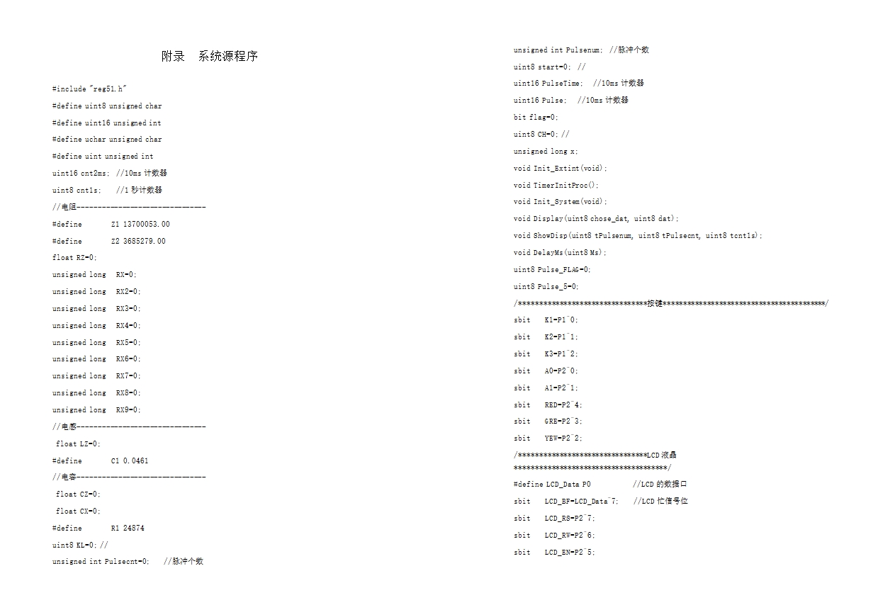
附录 系统源程序 29
致谢 41