
基于单片机的银行排队叫号系统设计
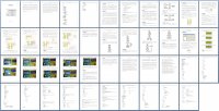
基于单片机的银行排队叫号系统设计(任务书,开题报告,外文翻译,论文12400字)
摘 要
银行里由于等候办理业务的人员众多,人员排队等待时间过久,如果可以设计一种机器人自动排队的系统,则将会大大减少排队人的辛苦。本文设计了一套智能排队叫号系统。该系统是以排队叫号顺序为核心,客户利用客户端取号,工作人员利用叫号端叫号;通过显示器及时显示当前所叫号数,客户及时了解排队信息,通过合理的程序结构来执行排队抽号。本文在硬件设计方面以89C52单片机为控制核心,利用矩阵按键以及4个直接按键,模拟客户取号和银行工作人员叫号;经过单片机对取号及叫号情况进行分析处理,最后传送到显示模块进行数据显示,同时进行语音播报提示。软件上主要使用KEIL软件编程,并对整个系统制作了实物模型。模型测试结果表明,系统工作正常,具有十分广阔的应用空间。
关键词:排队系统 单片机 LCD显示
Abstract
In banks, railway stations and other public places, due to the large numbers of people waiting to conduct business, if very hard to let people waiting in line ,if you could design a robot instead of human automatic queuing system, you will greatly reduce the queue of people hard .In this paper, design a set of line up your turn system. Queue smoke number sequence as the core, the system is based on the client using the client, staff using your turn end your turn; By timely display the current call number, timely understanding of line information, through the reasonable structure of program to perform the line number. In this paper, in the aspect of hardware design based on 89C52 single chip microcomputer as the control core, By using the matrix of keys and 4 direct key, Simulated customer take number and bank staff. After analysis of the SCM, and queuing situation, finally sent to the display module for data display At the same time, voice broadcast tips. The software mainly using KEIL software programming , and the entire system on the PROTEUS software to do the simulation. The simulation results show that the system is working properly, has a very broad application space.
[来源:http://Doc163.com]
Keywords : queuing system microcontroller LCD display
[来源:http://Doc163.com]

目录
摘 要 I
Abstract II
目录 1
第一章 引言 1
1.1研究背景及意义 1
1.2系统主要任务 1
1.3本文章节安排 2
第二章 硬件电路设计 3
2.1方案论证 3
2.2系统整体设计 3
2.2.1 取号部分系统设计 3
2.2.2 叫号部分系统设计 4
2.3单片机最小系统 5 [资料来源:http://Doc163.com]
2.4显示电路模块 6
2.4.1 显示器选择方案 6
2.4.2 12864液晶显示屏 7
2.4.2 1602液晶显示器 8
2.5语音播报模块 8
2.6 按键模块 9
2.7硬件设计总结 11
第三章 软件设计 12
3.1 系统总流程 12
3.1.1 取号部分系统流程 12
3.1.2 叫号部分系统流程 13
3.2 模块流程图介绍 13
3.2.1 1602显示模块 13
3.2.2按键扫描模块 14
3.2.3 串口配置模块 15
3.3 软件设计总结 15
第四章 系统调试及分析 16
4.1 PROTEUS仿真软件 16
4.2实物演示 17
4.3系统调试 22
4.3.1系统硬件调试 22
4.3.2系统软件调试 22
4.4本章小结 23
第五章 结论 24
致谢 25
参考文献 26
附 录 27
叫号部分系统代码 27
取号部分系统代码 35 [资料来源:https://www.doc163.com]