
基于PLC加热炉温度控制系统的设计(含CAD接线图梯形图)
基于PLC加热炉温度控制系统的设计(含CAD接线图梯形图)(论文说明书15000字,外文翻译,CAD图6张)
摘 要
本文主要介绍了工业温度控制的发展前景、S7-200系列PLC的基本知识以及锅炉温度控制系统的工作流程、基本原理和组成结构。通过对锅炉温度控制系统设计要求的分析,给出锅炉温度控制系统的I/O口分配表和系统原理图并且以可编程控制器(PLC)为核心,根据系统的控制要求利用STEP 7编程软件设计系统的梯形图。该系统以电热锅炉加热管为被控对象,锅炉水温为被控参数同时兼顾锅炉内压力及水位等条件,以PLC为控制器,锅炉加热管通电时间为控制参数设计了一个温度控制系统。其中调用了西门子公司PLC中自带的PID模块,以更简洁更方便的方法完成了锅炉温度的自动控制设计。本文从系统的工作原理、系统硬件选型、系统软件编程以及组态监控画面设计等方面进行阐述。
关键词: 电热锅炉;温度控制;PLC;PID;固态继电器
Design of temperature control system based on PLC heater
Abstract
This article focuses on the industrial development prospects of temperature control, basic knowledge of S7-200 series PLC as well as the boiler temperature control system made up of work processes, principles, and structure.Through the analysis of boiler temperature control system design, I/O port allocation table of temperature control system of the boiler,system schematics and a programmable logic controller (PLC) as the core, according to the control system requires the use of STEP 7 programming software system design of ladder diagram.The system to electric boiler heating tubes to a charged object, parameters of boiler water temperature to be controlled both the pressure and the water level in the boiler and other conditions, the PLC controller, boiler heating power parameter design of a temperature control system for control.Which is called the Siemens PLC comes with PID modules, and a more concise and more convenient way to complete the automatic control system design of the boiler temperature. This paper described the working principle of the system, system hardware selection, system software programming and configuration of the monitor screen design. [来源:http://www.doc163.com]
Keywords : Electric boiler; Temperature control; PLC; PID; Solid State Relays


目 录
摘 要 i
Abstract ii
1 绪论 1
1.1 课题背景及意义 1
1.2 国内外研究现状 1
1.3 本文研究内容 2 [资料来源:https://www.doc163.com]
2 温度控制系统设计 4
2.1 温度控制系统工作原理 4
2.2 PID控制及参数整定 4
2.2.1 PID控制原理 4
2.2.2 PID参数的整定 6
3 系统硬件设计 8
3.1 PLC的产生和特点 8
3.1.1 PLC的产生与应用 8
3.1.2 PLC的特点 8
3.2 PLC控制系统设计的基本原则和步骤 9
3.2.1 PLC控制系统设计的基本原则 9
3.2.2 PLC控制系统设计的一般步骤 9
3.3 系统整体设计方案 10
3.4 PLC选型 11
3.4.1 PLC的主机模块 11
3.4.2 PLC的I/O扩展模块 12
3.4.3 PLC的选择 12
3.5 传感器选型 12
3.5.1 温度传感器选型 12
3.5.2 PT100温度变送器选型 13
3.5.3 压力传感器选型 14
3.5.4 液位传感器选型 14
3.6 固态继电器 14
3.6.1 固态继电器的原理分析 14
3.6.2 固态继电器的组成 15
3.6.3 固态继电器的优缺点 15
3.7 数码管 16
3.8 系统工作流程及硬件接线 17
3.8.1 系统工作流程 17
3.8.3 系统主电路图 17
3.8.4 系统控制电路图 18
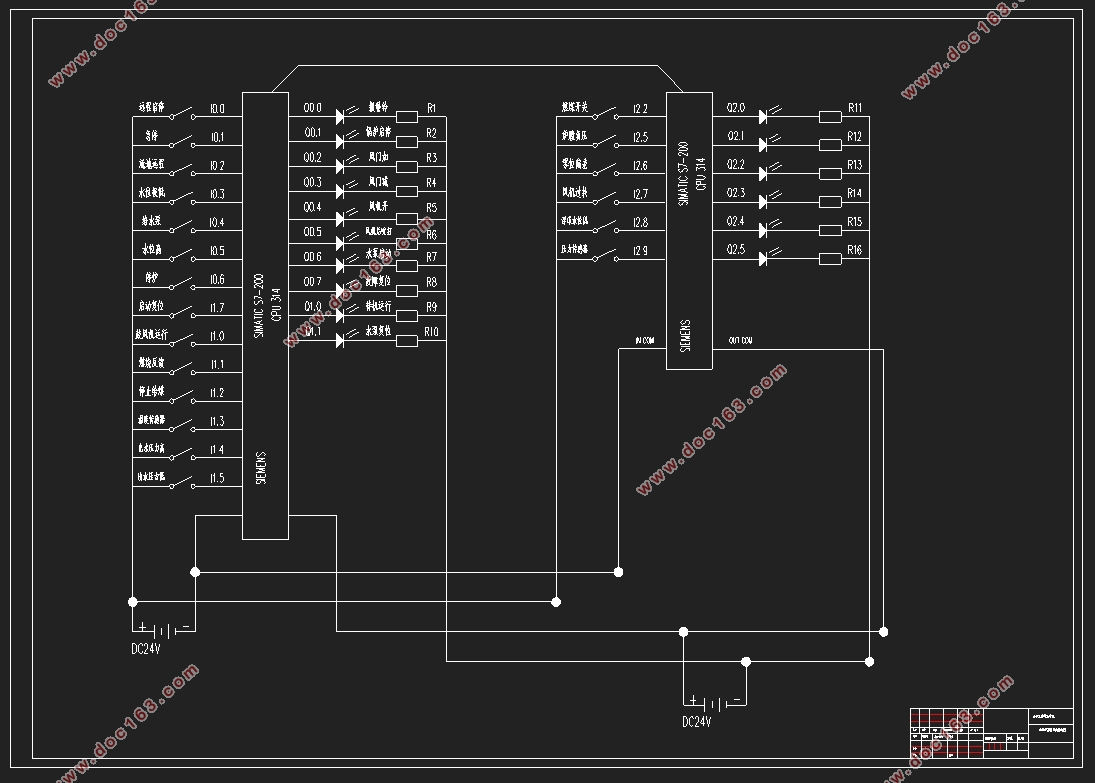
3.8.5 PLC硬件连接图 18
3.8.6 I/O端口分配 19
4 软件设计 21
4.1 主程序流程图 21
4.2 PID控制器的参数整定 21
4.3 PLC程序梯形图设计 26
5 人机界面设计 36
5.1 组态软件基础 36
5.1.1 组态定义 36
5.1.2 组态王软件的特点 36
5.1.3 组态王软件仿真的基本方法 36
5.2 组态变量的建立及设备连接 37
5.2.1 新建项目 37
5.2.1 新建设备 37
5.2.3 新建变量 38
5.2.4 变量与PLC的传输 39
5.3 创建组态画面 41
5.3.1 新建主画面 41
5.3.2 新建PID参数设定窗口 41
5.3.3 新建实时曲线 42
5.3.4 新建历史曲线 42
5.3.5 新建报警窗口 43
6 系统仿真及测试 44
6.1 系统运行 44
6.2 运行结果 44
6.2.1 参数设定画面 44
6.2.2 实时趋势曲线 45
6.2.3 历史趋势曲线 45
[资料来源:http://doc163.com]
6.2.4 报警窗口 46
结束语 47
附录1 源程序 48
附录2 组态图 62
参考文献 58
外文资料 61
中文译文 68
致谢 73 [版权所有:http://DOC163.com]
上一篇:煤矿排水控制系统PLC控制与组态(含CAD接线图梯形图)
下一篇:基于PLC的电动机故障保护系统设计(含CAD电气原理图梯形图)