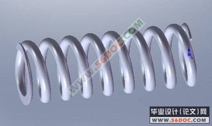
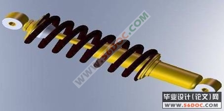
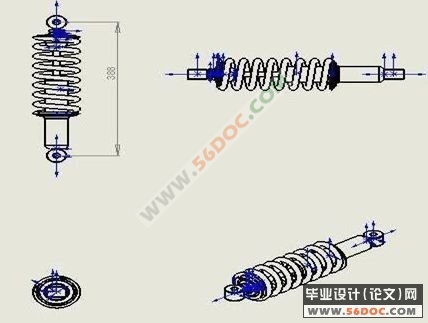
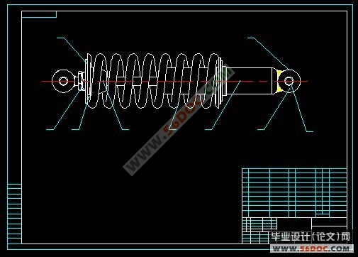
减震器的造型与设计(CAD图纸)

中文摘要
我的毕业设计主要是用Solidworks软件的造型,这也是此软件专业功能,它为机械产品造型提供了专业的模块,使设计变的更快、容易,CAD/CAM/CAE系统提供了一个基于过程的产品的设计环境,使产品开发从设计到产品成型的完美过度,Solidworks面向过程驱动的技术是虚拟产品开发的关键技术,在面向过程驱动技术环境中,用户的全部产品发及精确的数据模型能够在产品开发全过程的各个环节保待相关,从而有效的实现。产品我们选择了有效的材料作为产品的原料。在使用的过程中不会出现不必要的麻烦,让客户感觉到它的存在是很有必要的,我所做的造型的是车用减震器,这个产品用了弹簧钢、高速钢和丁睛橡胶作为产品的材料。
我所设计的造型是车用减震器,使用Solidworks对其造型,选择新建模型命令选项进入模型模块,同时在造型中有时需要进行修改或操作,使其在所有的零件造型完以后,在装配过程中不会出现不协调的情况,便于产生出2D视图和产品的爆炸图。
关键词:减震器 Solidworks 造型 设计 [资料来源:www.doc163.com]
Chinese summary
My graduation design main is the shape which use Solidworks software, this be also this software profession function, it provided for the machine product shape profession of mold piece, make design to change of sooner, easy, the CAD/CAM/CAE system provided 1 according to the product of process of design environment, make product development model from design to product of perfect excessiveness, the Solidworks face to process drive of technique is conjecture product development of key technique, drive technique environment in the process of face to in, customer of all product hair and precision of the data model can develop whole process in the product of each the link protect to treat related, thus valid of realization.The product our choice valid of the material be the raw material of product.Will not appear in the process of usage unnecessary of bother, let customer felling arrive it of existence is have much of necessity, the shape do by me of is vehicle-use to reduce earthquake machine, this product this product used a spring coil steel, high speed steel and D Jing rubber be the material of product. [资料来源:http://www.doc163.com]
I the shape for design be vehicle-use to reduce earthquake machine, usage Solidworks as to it's shape, choice new set up model order options to get into a model mold piece, in the meantime in the shape sometimes demand carry on modification or operation, make it at all spare parts shape over after, in the assemble the process will not appear not moderate of circumstance, easy to creation the 2 D see diagram and product of explosion diagram.
Key words: Reduce an Vibration machine Solidworks Shape Design [资料来源:http://doc163.com]


目 录 10000字
中文摘要 ••••••••••••••••••••••••••••••••••••••••••••••••••••••••••••••••••1
第一章 概述 ••••••••••••••••••••••••••••••••••••••••••••••••••••••••••••••5
1.1易于使用 •••••••••••••••••••••••••••••••••••••••••••••••••••••••••5
1.2 2D 到3D转换工具 •••••••••••••••••••••••••••••••••••••••••••••••5 [资料来源:http://www.doc163.com]
1.3、独特的功能 ••••••••••••••••••••••••••••••••••••••••••••••••••••5
1.4、零部件建模 ••••••••••••••••••••••••••••••••••••••••••••••••••••5
1.5、装配体建模 ••••••••••••••••••••••••••••••••••••••••••••••••••••5 [资料来源:http://doc163.com]
1.6、2D 工程图 ••••••••••••••••••••••••••••••••••••••••••••••••••••6
1.7、表面处理 ••••••••••••••••••••••••••••••••••••••••••••••••••••6
第二章 产品介绍 ••••••••••••••••••••••••••••••••••••••••••••••••••••7
[资料来源:www.doc163.com]
2.1 产品的作用及外形 •••••••••••••••••••••••••••••••••••••••••••••••••••7
2.2 产品的材料及物化性能 •••••••••••••••••••••••••••••••••••••••••••••••7
2.3分类 •••••••••••••••••••••••••••••••••••••••••••••••••••••••••••••••7
[资料来源:http://Doc163.com]
2.4 按照生产加工方法分类 ••••••••••••••••••••••••••••••••••••••••••••••••7
2.5 按照钢材交货状态分类 ••••••••••••••••••••••••••••••••••••••••••••8
2.6 其他分类方法 •••••••••••••••••••••••••••••••••••••••••••••••••••8
第三章 设计的主要要求和难点 •••••••••••••••••••••••••••••••••••••••••••••••••9
3.1 设计的主要要求 ••••••••••••••••••••••••••••••••••••••••••••••••••9
3.2 本次设计的难点 ••••••••••••••••••••••••••••••••••••••••••••••••••9
[资料来源:https://www.doc163.com]
第四章 减震器 ••••••••••••••••••••••••••••••••••••••••••••••••••••••••••••••10
4.1. 减震器弹簧造型 •••••••••••••••••••••••••••••••••••••••••••••••••10
4.2 减震器内柱的造型 •••••••••••••••••••••••••••••••••••••••••••••••••15 [来源:http://www.doc163.com]
4.3 构建实体内垫片、内套和内橡胶。 ••••••••••••••••••••••••••••••••••••••••20
4.4 垫片、螺帽、小垫片、橡胶皮和外套 ••••••••••••••••••••••••••••••••••••••22
第五章 减震器装配,爆炸图和工程图 •••••••••••••••••••••••••••••••••••••••••••30
5.1 减震器的装配图 ••••••••••••••••••••••••••••••••••••••••••••••••••30
[版权所有:http://DOC163.com]
5.2 装配后的工程图 ••••••••••••••••••••••••••••••••••••••••••••••••••32
总 结 ••••••••••••••••••••••••••••••••••••••••••••••••••33
致 谢 ••••••••••••••••••••••••••••••••••••••••••••••••••••••••••••••34
[资料来源:https://www.doc163.com]
参考文献 ••••••••••••••••••••••••••••••••••••••••••••••••••••••••••••••••35
