基于单片机的停车场管理系统设计

基于单片机的停车场管理系统设计(任务书,开题报告,外文翻译,论文13000字)
摘 要
随着经济的发展,车成为了人们生活中不可或缺的交通工具,而停车场更是越来越多,因此停车场的管理就格外重要。
本文设计了一个基于单片机的停车场管理系统,该系统以MFRC522非接触式读卡器芯片为基础,把STC89C52RC单片机芯片作为主控芯片的系统。当MFRC522读写器芯片读取到IC卡上的信息时,系统会去识别车辆的信息,接着控制电机的转动,以此达到模拟升降杆的目的。本文在提出设计的详细方案基础上,对各模块的软硬件设计进行了详细阐述,并对系统进行测试与调试。
测试结果表明,本文设计系统能实现所要求的功能。
关键字:单片机 停车场 IC卡识别
Parking management design based on single chip microcomputer
ABSTRACT
With the development of economy, the car has become an indispensable means of transportation, and the parking lot is more and more, so the management of the parking lot is very important.
In this paper,a parking management system based on single chip microcomputer is designed.The system is based on the MFRC522 contactless reader chip and the STC89C52RC chip is used as the main control chip.When the MFRC522 reader chip reads the information on the IC card,the system can identify the information of the vehicle,and then control the rotation of the motor to achieve the purpose of simulating the lifting rod.In this paper,based on the detailed scheme design,the hardware and software design of each module is described in detail,and the system is tested and debugged.
Test results show that the system can achieve the required functions.
Key word: single chip parking lot IC card recognition
[资料来源:http://www.doc163.com]


目录
基于单片机的停车场管理系统设计 2
摘 要 2
Parking management design based on single chip microcomputer II
ABSTRACT II
第一章 绪论 1
1.1 研究背景 1
1.2 国外现状与发展趋势 1
1.3 国内现状与发展趋势 2
1.4 研究目标和研究内容 2
1.4.1 研究的目标 2
1.4.2 研究的内容 2
1.5 论文的结构 3
[版权所有:http://DOC163.com]
第二章 系统方案的分析与选择 4
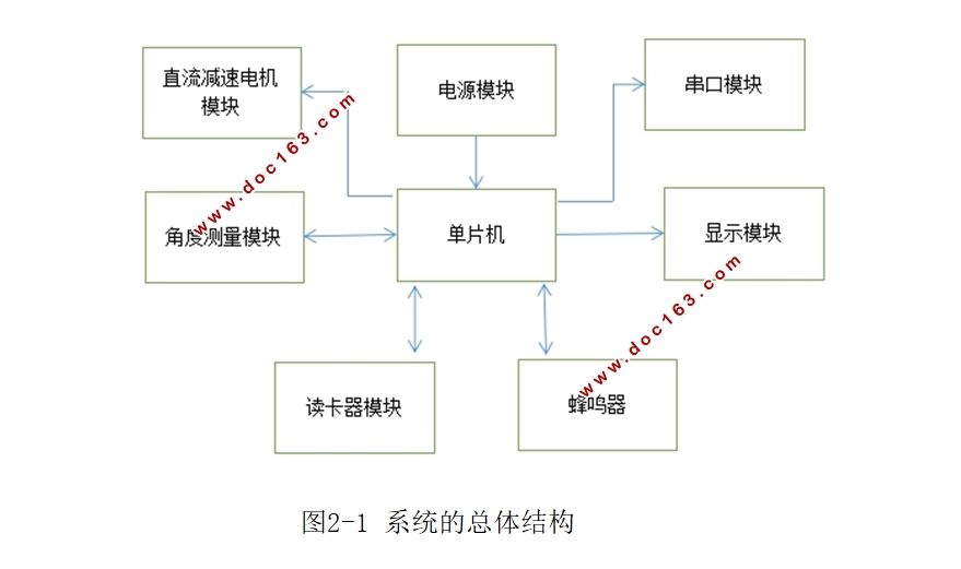
2.1 系统的总体结构 4
2.2 控制模块 4
2.3 显示模块 5
2.4 时钟模块方案 6
2.5 蜂鸣器方案 6
2.6 直流减速电机模块 6
第三章 系统的硬件设计 7
3.1 系统的主控电路 7
3.2 系统的时钟电路 8
3.3 复位电路 9
3.4 系统的电源电路 10
3.5 读写器电路 11
3.5.1 IC卡——Mifare One卡 11
3.5.2 读写芯片MFRC522 11
3.6 直流减速电机电路 13
3.7 直流减速电机角度测量及其转换电路 15
3.7.1 电位器测角原理 15
3.7.2 模数转换电路 15
3.8 液晶与指示灯显示电路 17
3.8.1 液晶显示电路 17
3.8.2 指示灯显示电路 19
[资料来源:Doc163.com]
3.9 按键电路 20
3.10 蜂鸣器电路 20
3.10.1 蜂鸣器介绍 20
3.10.2 蜂鸣器电路 21
第四章 系统的软件设计 22
4.1 主程序流程图 22
4.2 显示程序设计 22
4.2.1 读忙标志 22
4.2.2 写指令子函数 23
4.2.3 写数据子函数 23
4.2.4 LCD12864的初始化 24
4.3 MFRC522的读写卡程序 25
4.3.1 电机控制子函数 27
第五章 系统的调试 30
5.1 静态调试 30
5.2 动态调试 30
5.3 本设计中存在的问题 31
第六章 总结 32
6.1 结论 32 [资料来源:http://www.doc163.com]
