基于单片机的室内气体质量检测的设计

基于单片机的室内气体质量检测的设计(任务书,开题报告,论文11400字)
摘 要
随着互联网的发展,衍生出许多职业,这些职业在家就可以工作,比如网络购物、网络读书写作等。这也使得人们呆在室内的时间越来越长。室内作为一个封闭空间,虽然稍微屏蔽了室外空气的影响,但是室内空气流通性不好,容易造成室内污染的积累。并且人们在室内呆的时间太长,室内污染对人的影响还是很大的。
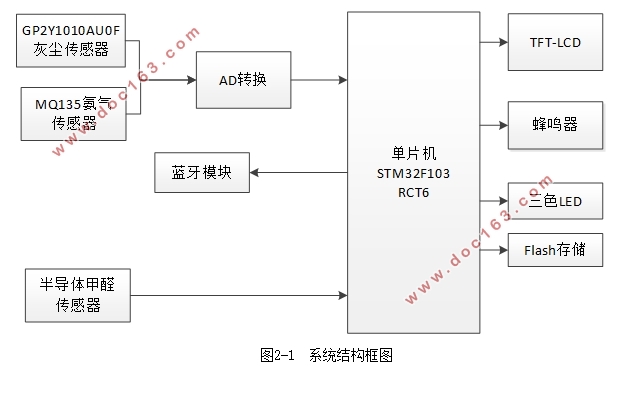
本设计采用STM32F103RCT6为控制处理器,运载一个16通道的12位模数转换芯片,2.8寸LCD,型号为W25Q64的8MB的flash芯片,型号为GP2Y1010AU的灰尘传感器,半导体甲醛模块,MQ135氨气传感器,和有源蜂鸣器,LED等器件。可以实现以下功能:对室内PM2.5、甲醛、氨气的测量,经过模数转换,在单片机中计算获得浓度值,在LCD上显示出来,如果超过上限,蜂鸣器和LED报警,之后对PM2.5的数据保存,蓝牙传输到上位机,在上位机上进行波形绘制。
关键词:STM32F103 气体传感器 模数转换 flash数据保存 上位机
Design of indoor air quality detection based on single chip microcomputer
Abstract
With the development of the Internet, derived from a number of career, these occupations can work at home, such as online shopping, online reading and writing.It also makes it more and more time for people to stay indoors.Indoor as a closed space, although slightly shielded the impact of outdoor air, indoor air circulation is not good, easy to cause the accumulation of indoor pollution.And people stay indoors for too long, the impact of indoor pollution on people is still very large.
This design adopts stm32f103rct6 for control processor, carrying a 16 channel 12 bit analog-to-digital conversion chip, 2.8 inch LCD, types of flash chip as the W25Q64 8MB, types of gp2y1010au dust sensor, semiconductor formaldehyde module, MQ135 ammonia gas sensor and active buzzer, led and other devices.A total of 9 small modules, you can achieve the following functions:on indoor PM2.5, formaldehyde, ammonia measurement, after the A / D conversion, in the monolithic integrated circuit calculation to obtain the value of the concentration, displayed on the LCD, if exceed the limit, alarm buzzer and led, after the PM2.5 data storage, Bluetooth transmission to the host computer, in the PC waveform drawing.
Key words: STM32F103;Gas sensor ;Analog digital converter ;Flash data storage ; Host computer


目 录
摘 要 I
Abstract II
第一章 引言 1
1.1 室内气体质量检测的研究背景 1
1.2 室内气体质量检测的研究现状 1
1.3 研究思路和技术方法 1 [来源:http://www.doc163.com]
1.4 内容安排 2
第二章 系统模块分析设计及确定 3
2.1 系统模块分析和设计 3
2.1.1 微处理器的选型 3
2.1.2 时钟方案 3
2.1.3 传感器模块的选型 3
2.1.4 模数转换 3
2.1.5 液晶显示模块的选型 3
2.1.6 报警模块的设计 4
2.1.7 存储芯片的选型 4
2.1.8 串口数据传输模块的选型 4
2.1.9 上位机编写的软件选择 4
2.2 最终系统方案 4
第三章 室内气体检测系统的硬件设计 6
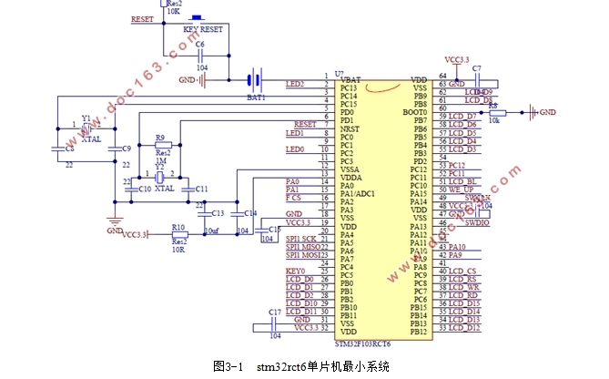
3.1 单片机最小系统 6
3.2 气体检测模块 7
3.2.1 PM2.5检测 7
3.2.2 半导体甲醛模块 8
3.2.3 MQ135传感器模块 9
[资料来源:http://Doc163.com]
3.3 TFT-LCD液晶显示模块 10
3.4 声光报警模块 11
3.5 RTC实时时钟 12
3.6 W25Q64存储模块 13
3.7 蓝牙模块 14
第四章 室内气体检测系统的软件设计 15
4.1 软件开发环境 15
4.2 AD转换 15
4.3 TFT—LCD液晶显示 16
4.4 报警模块 18
4.5 flash存储 19
4.6 上位机流程设计 20
4.6.1 串口接收配置流程设计 20
4.6.2 上位机数据处理流程设计 22
4.7 主程序流程 23
第五章 系统调试和结果 25
5.1 调试工具的选择 25
5.2 分模块调试 25
5.2.1 显示电路的调试 25
5.2.2 AD模块的调试 25 [版权所有:http://DOC163.com]
5.2.3 报警电路调试 26
5.2.4 实时时钟调试 26
5.2.5 蓝牙传输调试 26
5.2.6 存储模块的调试 27
5.2.7 PCB硬件系统焊接调试 28
5.3 系统运行结果 28
第六章 总结与展望 30
6.1 总结 30
6.2 展望 30
致 谢 31
参考文献 32
附录一 原理图 34
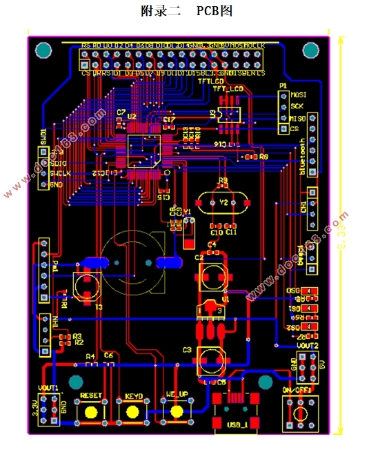
附录二 PCB图 35
附录三 实物图 36
