基于STC89C52的磁感应强度检测计的设计

基于STC89C52的磁感应强度检测计的设计(论文15000字)
摘要:本设计以STC89C52单片机为核心,采用NRF24L01模块和RS485模块传输,系统由无线传输和有线传输两部分组成,这两种传输方式可以使用按键自由切换。霍尔传感器采集到的信号,经ADC0832转换为数字信号,经过单片机的处理,NRF24L01和RS485的传输,最终在LCD1602上显示出磁感应强度。
硬件部分包括霍尔传感器采集模块、AD转换模块、无线传输模块、 显示模块、RS485模块、蜂鸣器报警模块。软件部分使用C语言进行编写,并使用KEIL软件进行系统程序设计,系统硬件电路原理图制作主要使用PROTEL 99 SE软件进行设计并制作PCB印制电路板图,待仿真成功后进行实物制作与调试,最后成功设计完成了磁感应强度检测计。该系统无线传输稳定,系统检测精度高,传输距离较远,使用也十分方便。
关键词:STC89C52;ADC0832;LCD1602;NRF24L01
Design of magnetic induction strength detector based on STC89C52
Abstract: This design with STC89C52 single-chip microcomputer as the core, uses RS485 module and NRF24L01 module transmission, the system consists of two parts, wireless transmission and cable transmission, these two transmission mode can use the button switch freely. The signal collected by hall sensor is converted to digital signal by ADC0832, and the transmission of NRF24L01 and RS485 is processed by MCU, and the magnetic induction intensity is finally shown on LCD1602. [资料来源:http://www.doc163.com]
The hardware part includes hall sensor acquisition module, AD conversion module, wireless transmission module, display module, RS485 module and buzzer alarm module. Software part use C language to write, and use the KEIL software system program design, system hardware circuit principle diagram making main using PROTEL 99 SE software for design and production of PCB, stay after the success of the simulation of real production and debugging, finally successful design completed the magnetic induction intensity testing meter. The system has stable wireless transmission, high accuracy of system detection, remote transmission distance and convenient use.
Key words: STC89C52; ADC0832; LCD1602; NRF24L01
[资料来源:http://www.doc163.com]


目 录
摘要 I
Abstract II
1 绪论 1
1.1 设计背景 1
1.2 开发现状 1
1.3 设计的意义与目的 1
2 系统方案设计 2
2.1 系统运行概述 2
2.2 无线传输模块的选择方案与论证 2
2.3 微控制器的选择方案与论证 3
2.4 显示屏的选择方案与论证 3
3 硬件设计 4
3.1 无线传输发射端 4
3.2 控制模块 4
3.3 传感器模块 6
3.4 ADC0832与单片机接口电路 7
3.5 NRF24L01部分 7
3.5.1 NRF24L01简介 7
3.5.2 NRF24L01管脚特性 8
3.5.3 单片机与无线模块的接口—SPI总线 8
3.5.4 NRF24L01和单片机接口电路 8
3.6 无线传输接收端 9
3.7 LCD1602与单片机接口电路 9
3.8 有线传输部分 10
3.9 RS485传输部分 10
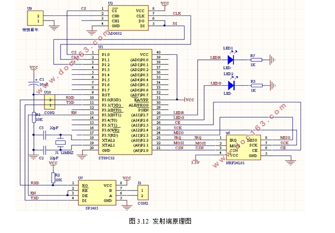
3.10 发射端和接收端原理图.................12
4 单元模块设计 13
4.1 蜂鸣器报警电路设计 13
4.2 电源自锁开关系统设计 14
4.3 按键系统设计 14
4.4 电压调节部分设计 15
4.5 LED状态指示部分设计 15
5 系统软件设计 16
5.1 软件开发环境介绍 16
5.2 系统总体流程图 17
5.3 无线传输发送程序功能介绍 18
5.3.1 数据采集子程序 19
5.3.2 无线发送模块子程序 19
5.4 无线传输接收端程序功能介绍 20
5.5 保护报警子程序 21
5.6 LCD1602显示模块子程序 22
5.7 按键扫描子程序 23
6 调试与检测 24
6.1 硬件的焊接 24
6.2 硬件测试 25
6.3 测试结论 27
7 总结与展望 27
7.1 总结 27
7.2 展望 27
参考文献 28
致谢 29
[资料来源:http://www.doc163.com]
