基于单片机信号检测系统设计

基于单片机信号检测系统设计(任务书,开题报告,外文翻译,论文13000字)
摘要
本文结合目前基于单片机信号检测系统的研究现状,以检测电压、电流、温度这三种日常生活中常见的信号为例,研究设计出硬件电路,编写出汇编语言程序,了解和掌握了51单片机及其外围硬件和软件,将理论知识与实践相结合,完成了对基于单片机信号检测系统的研究与探索。
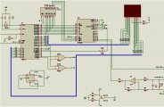
本次设计的主体部分分为两块,一部分是以单片机最小系统为核心的电压、电流信号检测系统,包含51单片机最小系统模块、ADC0809模数转换器模块、输出锁存模块、数码管显示模块、I/V转换电路模块、电压/电流信号选择模块;另一部分是以单片机最小系统为核心的温度信号检测系统,包含51单片机最小系统模块、数字温度传感器模块、数码管显示模块。
本次设计所做的主要工作如下:
(1)设计并绘制单片机最小系统电路图,单片机最小系统以AT89C51单片机为控制核心,包含复位电路和时钟电路两部分。
(2)设计并绘制电压、电流信号检测系统电路图。将组成本系统的各个模块依次拼接,按照电气规则完成连线。本系统的工作流程为:首先,将开关拨到电压档,输入模拟量电压信号,经ADC0809转换成数字量输送给单片机,单片机处理后,将数据输送给数码显示管显示电压值;然后开关拨到电流档,输入模拟量电流信号,经ADC0809转换成数字量输送给单片机,单片机处理后,将数据输送给数码显示管显示电流值。 [资料来源:https://www.doc163.com]
(3)设计并绘制温度信号检测系统电路图。将组成本系统的各个模块依次拼接,按照电气规则完成连线。本系统的工作流程为:数字温度计DS18B20检测温度并转变成数字量输送给单片机,单片机处理后,将数据输送给数码显示管显示温度值。
(4)分别编写两个系统的汇编语言程序,在Keil软件上调试编译并生成.hex文件,导入单片机最小系统,完成硬件电路图的仿真。
(5)总结经验,并对在本次设计中提供帮助的人表示感谢。
关键词:单片机;电压、电流信号;温度信号 ;汇编程序
Abstract
The article is based on the current research status of the signal -detection system with micro controller unit.To test the voltage, curr -ent, temperature of the three daily life of the common signal as an example, the study designed hardware circuit, compiled assembly language program, to understand and master the 51 micro-controller and its perip -heral hardware and software, the theoretical knowledge and practice phase Combined with the completion of the single-chip signal detection system based on the research and exploration. [来源:http://Doc163.com]
The main part of this design is divided into two parts, one part is the minimum system as the core of the microcontroller voltage and current signal detection system, including 51 single-chip minimum system module, ADC0809 analog-to-digital converter module, output latch module, , I / V conversion circuit module, voltage / current signal selection module; the other part is the minimum system as the core of the temperature signal detection system, including 51 single-chip minimum system module, digital temperature sensor module, digital display module.
The main work of this design is as follows:
(1) design and draw the minimum system circuit diagram of the microcontroller, single-chip microcomputer to AT89C51 microcontroller as the control core, including the reset circuit and the clock circuit in two parts.
(2) design and draw voltage and current signal detection system circuit diagram. Will be composed of the system of each module in turn splicing, in accordance with the electrical rules to complete the conne -ction. The system's workflow is: First, the switch to the voltage file, the input analog voltage signal, ADC0809 converted into digital transm -ission to the microcontroller, single-chip processing, the data will be sent to the digital display tube display voltage; To the current file, the input analog current signal, the ADC0809 converted into digital transmission to themicrocontroll -er, single-chip processing, the data will be sent to the digital display tube display current value.
(3) design and draw the temperature signal detection system circuit diagram. Will be composed of the system of each module in turn splicing, in accordance with the electrical rules to complete the connection. The system's workflow is: digital thermometer DS18B20 detection temperature and converted into digital transmission to the microcontroller, single-chip processing, the data will be sent to the digital display tube display temperature.
(4) respectively, the preparation of two systems assembly language program, in the Keil software debugging compilation and generate. Hex file, into the minimum system of single-chip, complete the hardware circuit diagram simulation.
(5) sum up experience, and thanks for the help the teacher provided.
Key Words:micro controller unit; voltage, current signal; temperature signal; assembler.
[资料来源:Doc163.com]


目录
1 概述 1
1.1课题研究背景 1
1.2 国内外研究现状 1
1.2.1国外研究现状 1
1.2.2国内研究现状 2
1.3设计目的及意义 3
1.4 本文安排 3
1.5 本章小结 4
2 设计方案的选择 5
2.1设计要求 5
2.1.1设计主要内容 5
2.1.2完成的主要任务及要求 5
2.2设计方案的确定 5 [资料来源:http://doc163.com]
2.2.1单片机模块 5
2.2.2电压/电流信号检测系统 6
2.2.3 温度信号检测系统 7
2.3 设计方案的评估 8
2.4 本章小结 8
3 硬件电路设计 9
3.1 AT89C51单片机最小系统 9
3.2 电压/电流信号检测系统 10
3.2.1 ADC0809模块 10
3.2.2 输出锁存模块 12
3.2.3电压/电流测量选择模块 13
3.2.4 I/V转换电路模块 13
3.2.5 数码管显示模块 14
3.3 温度信号检测系统 14
3.3.1数字温度传感器DS18B20 14
3.3.2数码管显示模块 15
3.4 本章小结 16
4 汇编语言程序设计 17
4.1 电压/电流信号检测系统 17
4.1.1程序设计流程图 17
4.1.2 模数转换部分程序 18 [资料来源:https://www.doc163.com]
4.1.3显示部分程序 19
4.1.4 延时程序 21
4.2 温度信号检测系统 21
4.2.1 程序流程图 21
4.2.2 部分程序 22
4.3 本章小结 24
5 仿真 25
5.1电压/电流信号检测系统 25
5.2 温度信号检测系统 26
5.3 本章小结 27
6 总结与展望 28
7 参考文献 29
致谢 31
附录A 电压电流信号检测系统电路图 32
附录B 温度信号检测系统电路图 33
附录C 电压电流信号检测系统程序 34
附录D 温度信号检测系统程序 36
