基于单片机的数字语音温度计

基于单片机的数字语音温度计(论文13000字)
摘 要
本文设计了一款操作简单,适用于多种场合的方便快捷的语音温度计。该设计的主控芯片采用AT89C51,LED数码管显示温度,蜂鸣器作为报警装置,通过语音存储芯片存储语音在播报的时候使用。本设计主要是通过温度传感器将温度的模拟信号转化成电流信号,然后以数字的方式显示在LED数码管上,可以检测的温度范围是-50℃~50℃,可以通过按键报出当前的温度,在日常情况下,它会在数码管上显示实时温度,另外还可以通过按键设置所需要的上下限值,当检测到的温度超过上限或者低于下限时,由蜂鸣器发出警报。
关键词: 数码管 温度计 蜂鸣器
Digital voice thermometer based on single chip microcomputer
Abstract
This paper designs a simple operation, simple and convenient voice thermometer is suitable for various occasions. The main control chip in this design adopts AT89C51, LED digital display of temperature, the buzzer as the alarm device, the voice memory chip storage of speech used in broadcast time. This design is mainly through the temperature sensor converts analog signal into a current signal of temperature, and then digitally displayed on the LED digital tube, the temperature range can detect is -50 ℃ ~ 50 ℃, the keys can quote the current temperature, in everyday situations, it can display real-time temperature in the digital tube, also can set the upper and lower limits required by key value, when the detected temperature exceeds the limit or below the lower limit, alarm by buzzer. [资料来源:Doc163.com]
Keywords: Digital tube The thermometer Buzzer
设计任务大致如下:
第一章主要是针对课题的研究背景以及课题的研究意义进行了详细的说明。
第二章从整体硬件设计出发,对各部分电路进行了详细说明,并介绍了设计中需要用到的主要器件;
第三章先给出了该设计的软件设计部分的主流程图,还对关键部分软件设计做了详细的解释;
第四章主要是系统完成后的调试和所遇到的问题;
第五章是结论。
系统总体设计方案
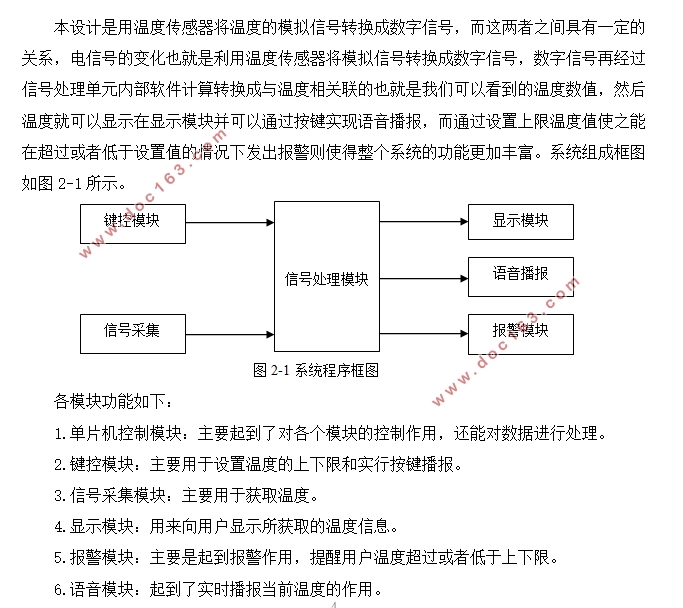
本设计是用温度传感器将温度的模拟信号转换成数字信号,而这两者之间具有一定的关系,电信号的变化也就是利用温度传感器将模拟信号转换成数字信号,数字信号再经过信号处理单元内部软件计算转换成与温度相关联的也就是我们可以看到的温度数值,然后温度就可以显示在显示模块并可以通过按键实现语音播报,而通过设置上限温度值使之能在超过或者低于设置值的情况下发出报警则使得整个系统的功能更加丰富。
[资料来源:www.doc163.com]


目录
摘 要 I
Abstract II
第一章 绪 论 1
1.1 课题研究的意义 1
1.2 课题设计的背景 1
1.3 课题设计的任务 2
第二章 硬件电路设计 4
2.1 系统总体设计方案 4
[来源:http://www.doc163.com]
2.2 系统处理模块 5
2.2.1方案选择 5
2.2.2芯片介绍 5
2.2.3时钟、复位电路 6
2.3 温度采集模块 8
2.3.1芯片介绍 8
2.3.2温度采集电路 8
2.4 显示模块 9
2.4.1方案选择 9
2.4.2芯片介绍 9
2.4.3显示模块电路 10
2.5 键盘控制模块 11
2.6 语音播报模块 12
2.6.1芯片介绍 12
2.6.2语音模块电路 12
2.7 报警模块 13
第三章 软件设计 15
3.1 系统主流程图 15
3.2 主程序 16
3.3 温度数据获取 18
3.4 显示程序 20
3.5 按键程序 20
3.6 报警程序 23
第四章 硬件调试及结果 26
4.1 硬件电路 26
4.2 硬件电路调试 26
4.3 调试过程中遇到的问题 28
结束语 29
致谢 30
参考文献 31
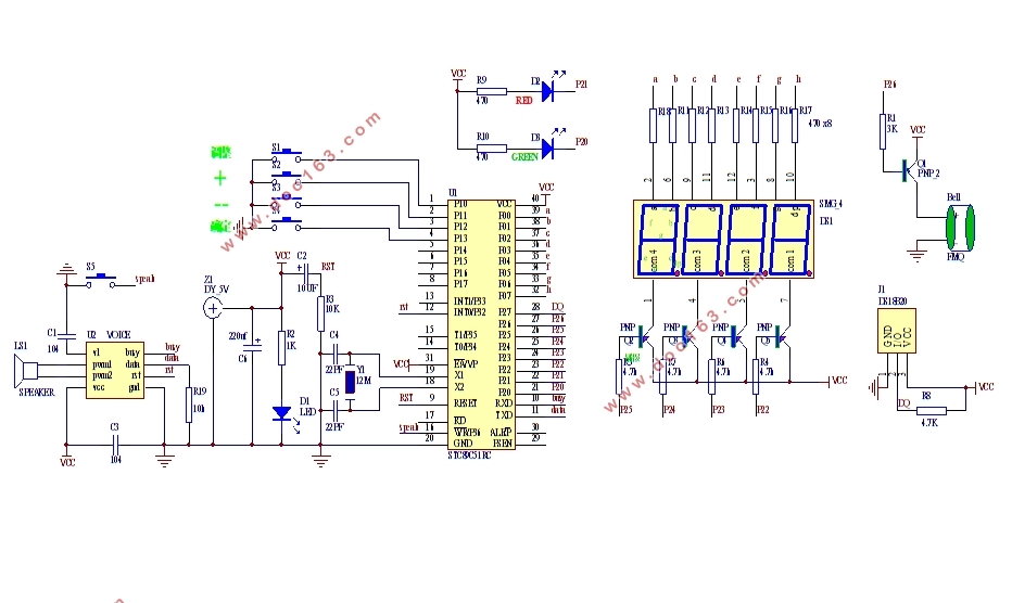
附录1 系统总体电路图 32
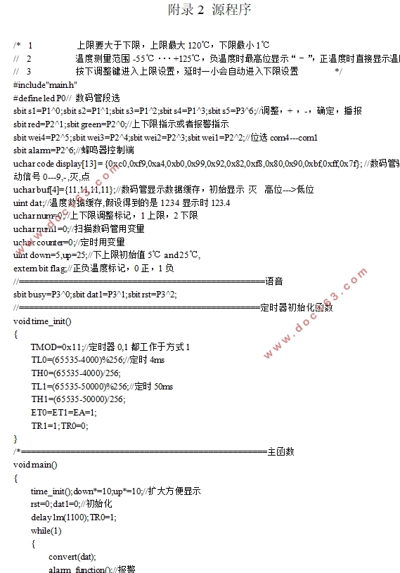
附录2 源程序 33
