
数字式人体脉搏仪的设计(STC89C51RC)(附系统原理图,PCB图,代码清单)
数字式人体脉搏仪的设计(STC89C51RC)(附系统原理图,PCB图,代码清单)(论文9000字)
摘要:随着时代的发展,社会在前进,人们的物质条件逐步提升,然而却引发了很多疾病,甚至很多人的生命被它们夺走,例如冠心病等人们防范较为困难的心血管疾病,所以身体健康也变为了现代社会广泛关注的问题之一。本次设计的主要目的就是设计一款可以随时随地测量出脉搏数值的便携数字式人体脉搏仪。本系统将STC89C51RC当成脉搏仪的核心单元,检测人体动脉搏动产生的微弱脉冲信号通过红外传感器,运用软硬件双重滤波及LM358双运算放大器放大信号的方法实现对人体脉搏信号的精确测量,最终通过C语言编写的程序将数据显示在LCD1602的屏幕上。
关键字:脉搏仪,STC89C51RC,C语言
Design of digital human pulse device
Abstract: With the development of the times, society is advancing, and people’s material conditions have gradually increased. However, many diseases have been caused. Even many people’s lives are taken away by them. It has also become one of the issues of widespread concern in modern society. The main purpose of this design is to design a portable digital human pulse meter that can measure the pulse value anytime anywhere. This design uses the STC89C51 microcontroller as the main control chip of the pulse meter, uses the infrared sensor to detect the signal, uses the hardware and software double filter and the LM358 dual operational amplifier to amplify the signal to achieve accurate measurement of the human pulse signal. After many experiments, the design is low-cost, simple to use, easy to carry, and basically meets the design requirements. [来源:http://www.doc163.com]
Keywords: pulse meter, single-chip STC89C51, infrared sensor, LM358
[资料来源:www.doc163.com]
目 录
一、引言 1
1.1 研究背景和意义 1
1.2 研究现状及发展动态 1
二、方案设计及论证 1
2.1 研究内容及设计指标 1
2.2 模块方案设计与论证 2
2.2.1 传感器的选择与论证 2
2.2.2 信号处理方案选择和论证 2
2.2.3 显示模块选择和论证 3
2.3元器件选择及其功能介绍 3
2.3.1单片机STC89C51RC 3
2.3.2红外传感器 4
2.3.3双运算放大器LM358 5
2.3.4 LCD1602显示模块 5
三、硬件系统设计 6
3.1 硬件系统设计框图 6
[来源:http://Doc163.com]
3.2 信号采集电路 6
3.3 信号放大电路 7
3.4 信号比较电路 7
3.5 LCD1602显示电路 8
3.6 键盘电路 8
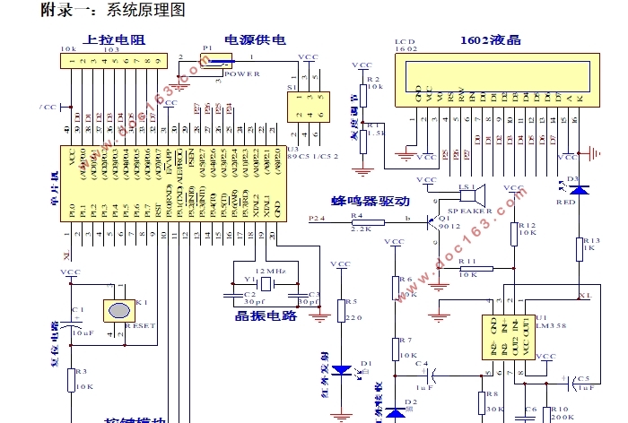
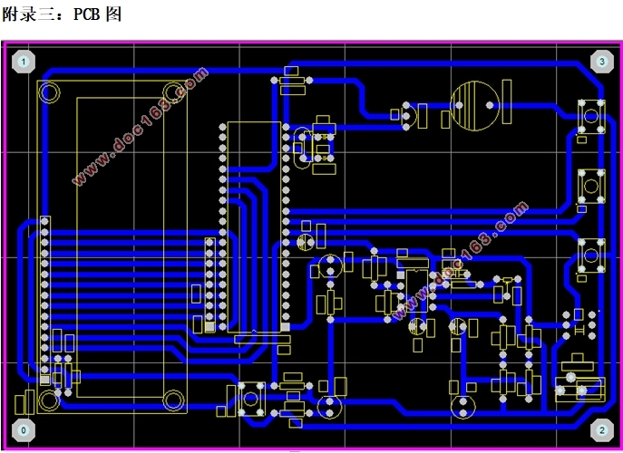
3.7 总体电路图及PCB绘制……………………………………………………………9
四、软件系统设计 10
4.1 测量计算原理 10
4.2 主程序流程图 10
4.3 中断程序流程图 11
4.4 定时器T0,T1的中断服务程序 11
4.5 串口初始化 ……………………………………………………………………12
4.6 LCD1602程序 ……………………………………………………………………12 [资料来源:Doc163.com]
4.7 上位机程序设计 . ………………………………………………………………13
五、系统测试与结果分析 15
5.1 测试方法和仪器 15
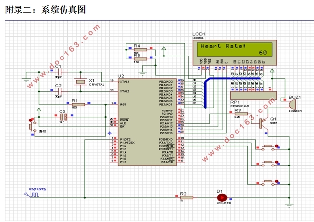
5.2 仿真与焊接阶段 15
5.2.1 电路仿真 15
5.2.2 焊接与完成阶段 18
5.3 测试传感器及按键功能 ………………………………………………………19
5.4 测试数据与结果分析 20
5.5 上位机软件测试………………………………………………………………….21
六、总结与展望 21
参考文献 22
致谢.................................................................23 [来源:http://Doc163.com]
上一篇:基于单片机的脉搏测试仪的设计