基于单片机的数字钟设计(附程序,电路图)

基于单片机的数字钟设计(附程序,电路图)(外文翻译,论文19000字)
The design of digital clock based on signal-chip computer
摘 要
基于单片机的定时和控制装置在许多行业有着广泛的应用,而数字钟是其中最基本的,也是最具有代表性的一个例子。
在基于单片机系统的数字钟电路中,除了基本的单片机系统和外围电路外,还需要外部的控制和显示装置。本电路主要以单片机AT89S52为核心而设计的,通过单片机对信息的分析与处理,控制外围设备。系统由复位模块、时钟模块、温度模块、音乐模块、光识模块及显示模块共六个模块组成,后来在时钟模块的基础上又加载了日历、星期的模块。
本设计以单片机AT89S52为切入点,通过使用AT89S52的内部的可编程定时器/计数器,结合对外接晶振的调节来确定一个合适的振荡周期,从而确定出内部的机器周期。再通过对内部中断程序的设置来设计出时钟程序,即设计出了电子时钟的核心。然后在核心电路的基础上设计出了相应的扩展电路,使本设计更加实用。
关键词:单片机;数码显示;温度传感器
ABSTRACT
The timer equipment using micro controller unit is applied in many trades, the digital clock is the most fundamental example among them, and it is also a most typical example. [资料来源:http://Doc163.com]
In digital clock circuit based micro controller unit system, there are the external controlling and display device besides the fundamental monolithic machine system and the outer-ring circuit. The key of the circuit in this design is AT89S52, using the micro control system to process information to control the outer-ring circuit. The system is made up of circuit, clock circuit, music circuit, temperature circuit, and shine circuit. Date and week modul is the external part.
This design focuses on monolithic integrated circuit AT89S52. Using AT89S52, which has the interior programmable timer/counter, the union foreign meets the crystal oscillator the adjustment to determine an appropriate duration of oscillation, thus determines theinterior the cycle of the system. And designing the internal interrupt procedure establishment to design the clock procedure, namely designed the core of electronic clock. Then design the expanded electric circuit to let this design more practical.
Key Words:Micro control unit; LED shows; Sensor of temperature [资料来源:http://doc163.com]
[版权所有:http://DOC163.com]


目 录
1. 引言 1
2. 关于单片机 2
2.1单片机的发展 2
2.2 单片机的开发背景 4
2.2 单片机的开发背景 5
2.3 AT89S52单片机 6
2.3.1 AT89S52单片机引脚功能 7
2.3.2 AT89S52单片机硬件结构的特点 8
2.3.3 AT89S52单片机的硬件原理 10
3. 方案设计与论证 12
4. 系统总体结构框图 13
5. 系统的硬件设计 14
5.1 显示部分电路的设计 14
5.1.1 LED数码显示管的基本原理 14
5.1.2 数码管显示模块分析 14
5.1.3 LED显示电路 15
5.2 控制部分电路的设计 15
5.2.1 时钟模块 15
5.2.2 温度模块 16
5.2.3 音乐模块 16
5.2.4 复位模块 16
5.2.5 光识模块 17
6. 系统的软件设计 18
6.1 各模块的程序设计 18
6.1.1 计时程序 18
6.1.2 定时闹钟程序 18
6.1.3 温度程序 18
6.2 系统程序设计的总体框图 19
7. 系统电路的制作与调试 20
7.1 电路硬件焊接制作 20
7.2 调试的主要方法 20
7.3 系统调试 20
7.3.1 硬件调试 20
7.3.2 软件调试 20
7.3.3 联机调试 21
7.3.4调试中遇到的问题及解决方法 21
结论 23
参考文献 24
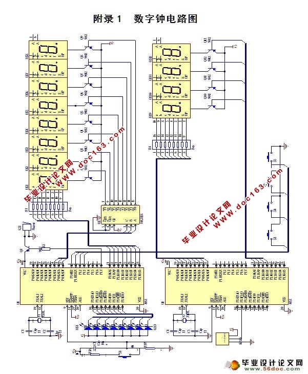
附录1 数字钟电路图 26
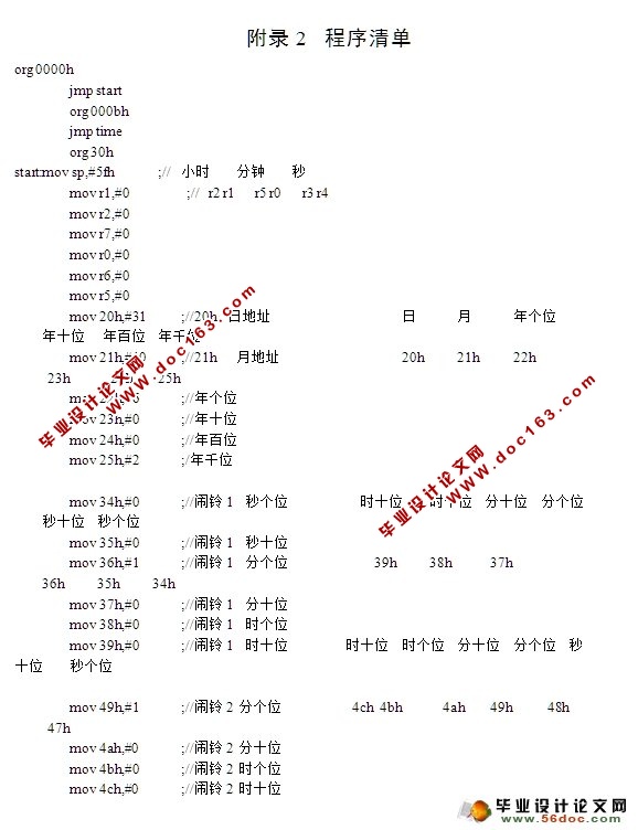
附录2 程序清单 27
附录3 英文资料 59
附录4 英文资料翻译 69
致谢 77
上一篇:基于单片机的数字温度计
下一篇:基于单片机的水温控制系统设计
